Continue to Site

Welcome to our site!

Electro Tech is an online community (with over 170,000 members) who enjoy talking about and building electronic circuits, projects and gadgets. To participate you need to register. Registration is free. Click here to register now.

  • Welcome to our site! Electro Tech is an online community (with over 170,000 members) who enjoy talking about and building electronic circuits, projects and gadgets. To participate you need to register. Registration is free. Click here to register now.

Generating a current between 0 - 250 mA for a load up to 40 ohms

Status
Not open for further replies.

VerifEng

New Member
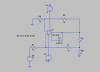
I'm trying to use a howland current source to generate stable current for a load which is =<40 ohms. The load is connected to ground but I can't find the appropriate gain to help me achieve this. I can work with a DAC to supply the Vin (V3 in the figure), which would help me control the load current, however, I'd like to limit the voltage used as input to 12V if possible.


I tried to use a LT3080 with digital potentiometers but had great difficulty in the lab implementing the circuit
 

Attachments

  • Screen Shot 2020-01-20 at 7.47.18 PM.png
    Screen Shot 2020-01-20 at 7.47.18 PM.png
    59 KB · Views: 190
Last edited:
Does the load have to be grounded, or could it be connected in line with other components?

eg. can it have a current sense resistor between load ground and power ground? That makes it simple, sensing elsewhere is slightly more complex.
 
Thanks for your help. I realized that I was trying to achieve something not possible and misunderstood the problem at hand.
 
Last edited:
The goal is to control the current through a Raspberry Pi
The RPi current will naturally depend on its workload and which of its features/peripherals are in use. Won't trying to control the current impact the Pi's performance?
 
the LT3080 was just not reliable and would fluctuate too much.
How much does it "fluctuate"?

Below is the LTspice simulation of a Howland circuit with a load of 0.1 ohm to 50 ohm for a sinewave input of 0V to 2.5V peak.
I had a problem getting an accurate constant-current with the LT1206, so I used a standard rail-rail opamp with a transistor emitter-follower booster to get 250mA.
I scaled the circuit gain so that 2.5V in gives 250mA out.
This gives a constant load current of 0-250mA (red trace) and goes above 12V output, at over a 50 ohm load.
Note that you obviously can't get 12V output with only a 5V supply, you need a plus supply of at least 15V.

1579637914588.png
 
Thank you for your reply. What I meant by that, is implementing this circuit in the lab was not giving me proper results. I struggled to obtain the correct current. Which is why I started to look at this circuit.
 
as I was trying to work with the howland current pump circuit, someone recommended me this circuit. Would there be any problems implementing it in the lab?

I can set Vref to ground, and Rref to 1 ohm. From there, I can control the current going across RL as long as my amplifier is able to amplify to the voltage across the Resistor.


Screen Shot 2020-01-21 at 4.07.22 PM.png
 
someone recommended me this circuit.
That's okay as long as your load can float and doesn't need to be connected to ground.
 
Last edited:
You could add an emitter follower at the output of the opamp, to increase the load current capability.

You need adequate supply voltage "headroom" to allow for whatever maximum the opamp you choose can give, plus at least 0.7V for the emitter follower.

At 250mA through 40 ohms, 12V will be tight, but may be possible.

The approach I was thinking of, which I have used in the past, is a PNP transistor feeding power to the load from the supply and the sense resistor between the load and 0V.

Compare the sense voltage to the DAC voltage with the opamp (sense to + in and DAC to -in, and the opamp drives the transistor base via a resistor, with another resistor base-emitter to bypass any leakage.

That allows virtually full voltage across the load.
 
so. .25A across 40 ohms will be 10V... the load will dissipate 2.5W. crutschow's circuit would be our best bet since most op amps will have a difficult time sourcing 250mA. some kind of current boosting will be required. in crutschow's circuit, the transistor is inside the feedback loop, and your voltage feedback is developed by the current through the load.
 
so. .25A across 40 ohms will be 10V... the load will dissipate 2.5W. crutschow's circuit would be our best bet since most op amps will have a difficult time sourcing 250mA. some kind of current boosting will be required. in crutschow's circuit, the transistor is inside the feedback loop, and your voltage feedback is developed by the current through the load.

Thank you for some clarification. I’ll keep that in mind.
 
Here are the files.
Change the txt extension to .lib.
The asy extension file goes in the sym\Opamps folder, and the .lib extension file goes in the sub folder.
 

Attachments

  • LMC6484A.asy
    817 bytes · Views: 168
  • LMC6484A.txt
    3.3 KB · Views: 149
Btw, crutschow, in your design, would it be possible to replace the sine wave for the DAC? I'm under the impression all the current is getting drawn from the power supply and not the V3 source.
 
Thank you. Would you also have the one for the transistor?
That can be just about any BJT that can handle the current.
, @crutschow, in your design, would it be possible to replace the sine wave for the DAC? I'm under the impression all the current is getting drawn from the power supply and not the V3 source.
Yes.
The V3 is just the reference voltage that controls the current provided by the op amp/transistor.
 
crutschow great, thanks. I tried the circuit I suggested but I used the LT1206, it wasn’t amplifying properly the signal. I believe it’s because it was a current feedback amplifier and not a voltage feedback amplifier, that’s what I was told. I’m going to try the circuit again with a new amplifier and I’ve bought the components to try this circuit. thanks again for your help
 
Status
Not open for further replies.

Latest threads

New Articles From Microcontroller Tips

Back
Top