Continue to Site

Welcome to our site!

Electro Tech is an online community (with over 170,000 members) who enjoy talking about and building electronic circuits, projects and gadgets. To participate you need to register. Registration is free. Click here to register now.

  • Welcome to our site! Electro Tech is an online community (with over 170,000 members) who enjoy talking about and building electronic circuits, projects and gadgets. To participate you need to register. Registration is free. Click here to register now.

Generating 38kHZ wave with a PIC13XX

Status
Not open for further replies.
August,
Thanks for posting the code.

Krumlink has the detector working using the PIC generated output. Krumlink had the hardware and I used to simulator to kludge up the code for/with him.

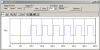
We used processor cycles. Delay_10CTx(10) plus a few nop's to tune it. I used the simulator LA to get the timing close. Thinking is is + or - 4 cycles out of 220 or so.

I want to thank whoever (maybe Nigel?) mentioned that it was not a good idea to send a steady stream of 38KHz.

The C18 file is far from polished but I have included it in case anyone wants to see it.

All is well with the world. For now.
 

Attachments

  • main.c
    1.4 KB · Views: 170
Yes, by sending 1000 cycles of 38khz at a time, then delaying for 18000 cycles, the reciever (radioshack parts LOL) was able to pick it up quite well, despite the long leads and the breadboard. I am currently designing a PCB with everything nice and pretty. It will be a 4x2 board. :)
 
Hi I have small questions regarding to this thread.

Most IR sensors working on 38KHz range is this sine wave or square wave?
or only the career signal is sine wave?Or both square waves?

There are two wave forms in a TV remote signal career wave & data.

Tell me a I right?
 
Square wave. It's a digital signal, and yes there is a 38KHz carrier and much slower data.
I've posted this simple IR jammer code :) in another similar thread.
Code:
// 37.7KHz IR carrier
#include <p18f1320.h>
#pragma config WDT = OFF,OSC = INTIO2,LVP = OFF
void main(void) {
    OSCCON=0x72;
    ADCON1 = 0;  
    TRISBbits.TRISB3 = 0;
    PR2 = 0b00110100 ;
    T2CON = 0b00000100 ;
    CCPR1L = 0b00011010 ;
    CCP1CON = 0b00011100 ;
    while(1) {
     }    
}
Put an IR LED on RB3 and it transmits a constant 37.7KHz carrier.
This RC5 data with carrier from http://www.sixca.com/eng/articles/remote/index.html
**broken link removed**
 

Attachments

  • PWMJunebug.png
    PWMJunebug.png
    7.5 KB · Views: 157
Last edited:
Hi thanks for the info

So no any sine waves involved. That’s nice.

The logic “1” & “0” represent by long burst of career frequency.
 
I would set the duty to 0% for a zero; then to 50% for a 1. The 38KHz is a carrier (envelope) for the data, as long as the data timing is correct the IR decoder will strip away the carrier automatically and pass the raw data to the PIC.

Hi I have taken your earlier post from other thread.

If its strip the carrier frequency then where is the data?

Because the data is the collection of carrier frequency.

I’m confused
 
Well here's the data, the carrier would be the black boxes. The IR demodulators output would look like this.
**broken link removed**
 
There are more than one form of IR coding, in fact most IR coding is from one of the three main varieties. If you don't know which one to use, you are wasting your time trying to code or decode them as they are not compatible to each other.

All three use approximate 36~40KHz carrier frequency so the detector module can be the same at close range of a few inches, but one need to use the designated frequency IR module in order to have ranges in feet and meters.

The data is modulated into the carrier via one of the following ways:

1. a fixed carrier ON time and changing OFF time to represent "1" or "0"

2. a fixed carrier OFF time and changing ON time to represent "1" or "0"

3. order of carrier ON/OFF time in a pair and which comes first to represent "1" or "0"

Identify which type of signal you want to use first before rushing into your code/decoding method.

Edited: Carrier ON time is constant carrier for a certain time, usually multiple of one IR carrier full period, carrier OFF time is the absence of carrier. In another word, the remote control IR LED is blinking at 38KHz to mean carrier ON, OFF to mean carrier OFF.
 
Last edited:
eblc1388 said:
All three use approximate 36~40KHz carrier frequency so the detector module can be the same at close range of a few inches, but one need to use the designated frequency IR module in order to have ranges in feet and meters.

I can't say I've ever found that?, I've only ever stocked one type of IR receiver which I use to replace faulty ones in all types of TV's - and they always work perfectly well, with ranges exceeding 13 metres (which is the length of the service department).
 
Our programmer for the robotics team (494) spent many hours getting our gyro and IR to work, and we have REALLY done well. With a IR reciever similar to the junebug, we can easily detect it from over 50+ feet away with a standard remote through a 1/8 piece of lexan too.

Also I am working on finding the ideal range of IR pulses, just so that the IR reciever can recieve a long enough burst to trigger, yet short enough to not reduce the strengh of the outupt. I am thinking 1000 cycles with a 4000 cycle wait time. I will have to try this out tomorrow (have to babysit (MONEY :D) and robotics meeting :D)
 
I need help with this too..I need to generate optical test signal for tsop38338
So i neen 23 times 13us log1, then 13us log0, and then 600us log0, and repeat. This should generate square wave on the TSOP receiver. I tried with simple delays but it's not working. Can someone help me? I'm using boostC, and i would prefer to do it in C oposed to asm.

Thanks

Edit: I'm using 16f877A and 4MHz clock
 
Last edited:
I need help with this too..I need to generate optical test signal for tsop38338
So i neen 23 times 13us log1, then 13us log0, and then 600us log0, and repeat. This should generate square wave on the TSOP receiver. I tried with simple delays but it's not working. Can someone help me? I'm using boostC, and i would prefer to do it in C oposed to asm.

Thanks

Edit: I'm using 16f877A and 4MHz clock

Check my tutorials for assembler solutions - it's VERY, VERY simple to do.

C is likely to be much more difficult, as you don't know what code is going to be produced, but you should be able to include assembler portions for the time critical parts.
 
hi nigel

i looked at your tutorials. Looks ok, i still have to try it. Do you have any schematics somewhere, or just the code(tut 5)?
 
Status
Not open for further replies.

Latest threads

New Articles From Microcontroller Tips

Back
Top