Continue to Site

Welcome to our site!

Electro Tech is an online community (with over 170,000 members) who enjoy talking about and building electronic circuits, projects and gadgets. To participate you need to register. Registration is free. Click here to register now.

  • Welcome to our site! Electro Tech is an online community (with over 170,000 members) who enjoy talking about and building electronic circuits, projects and gadgets. To participate you need to register. Registration is free. Click here to register now.

Gear indicator for chinese motors

Status
Not open for further replies.

eldergeek

New Member
I have a 110cc Chinese motor made by Lifan. It has four gears and a selector switch for gear indication that unlike some gear selectors I have read on this forum that have a variable output, this closes to ground for each gear. I was wanting to build a gear indicator using a small seven segment display. The SSD only needs to display five digits. 0, 1, 2, 3, 4. (and maybe a 'test' to light all segments)

The end result is when the motor is in Neutral, '0' is displayed, first gear '1', and so on.

I have been searching and reading about SSD, 4511 & 7446 decoders, Truth Tables, BCD, Binary and I am getting confused. I thought this would be a rather easy project but I am finding it may not be. The alternative is to skip the SSD and use seperate LEDS for each gear. That's cheesier than I want to do so I need a diagram showing how to make this happen and what components, (decoder/driver?) to use.

There seems to be many SSDs out there. I understand common Cathode/Anode. Is there one that is flush mounting? Looking in the size range of about 1/2-3/4 tall digits. It needs to mount on or near handle bars/gauge cluster.

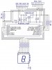
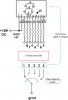
Here is a quick diagram of what I think I need.


Any links or input is appreciated!
 

Attachments

  • gear display.jpg
    gear display.jpg
    82.6 KB · Views: 1,881
The simplest solution is to use a bunch of diodes.

You need a diode for each segment, for each gear. So for neutral (0), you need 6 diodes. The cathodes are all connected to the neutral connection on the switch and the anodes are connected to the resistors for segments a - f. 1st gear needs 2 diodes, with both cathodes connected to the 1st gear connection on the switch and the anodes connected to the resistors for segments b and c.

And so on.

I make it 23 diodes in all. You could use 1N4001 diodes that cost a few cents each.

You could do it with fewer components, if you used the decoders or even a microcontroller, but finding out how to do that would take a lot longer.
 
Driver300, I thought of that too. I need to see how big that board would be as size is a factor too. It needs to be small to fit under the seat or gas tank. I was hoping a decoder/MC design would allow fabbing a small board in a box I could hide somewhere and run the outputs to the SSD to the bars. Though it may be bigger than a pile of diodes. :)

I'm in no rush so if it takes some time thats fine.
 
You could use a CD4532B (or similar) 8 input priority encoder to convert the gear positions to a 3-bit binary code, and then a CD4511 (or similar) to convert the binary (BCD) to a 7-segment display output.

Since the gear indicator switches go to ground you will need to add an inverter (CD4009) to give the proper logic high signal to the encoder inputs when the switch is grounded. Use a 10k pull-up resistor to V+ on each switch output to generate the switch voltage levels to the inverter inputs.

Edit: Make sure all unused inputs on the CMOS circuits are tied to ground or V+. Do not leave any inputs floating.
 
Last edited:
Driver300, I thought of that too. I need to see how big that board would be as size is a factor too. It needs to be small to fit under the seat or gas tank. I was hoping a decoder/MC design would allow fabbing a small board in a box I could hide somewhere and run the outputs to the SSD to the bars. Though it may be bigger than a pile of diodes. :)

I'm in no rush so if it takes some time thats fine.
If you decide to go the microcontroller route then a PIC16HV610 would be a good candidate, as long as the MCLR pin is used as an input. The PIC HV series have an internal 5V shunt regulator, max 90ma combined port currrent.

Operation would include scan/poll the five gear inputs (with weak pullups) and source the micro's 5V ouputs to the appropriate segments (i.e. CC display). Everything should fit behind the SSD, in a small enclosure, with wires going to gear switch, 12V, and gnd (like a mini 8 pin din cord).
 
Last edited:
I do appreciate both of your suggestions, however, I see I need to do even more reading as most of what both of you posted is above my skill set. lol.... I have no clue how to code/configure these devices. Do I need a $900 programmer for the PIC16HV610?? edit: did some more reading, doesn't look like it.

Everything should fit behind the SSD, in a small enclosure, with wires going to gear switch, 12V, and gnd (like a mini 8 pin din cord).

That is what I had in mind NickleFlippr. I can solder everything together and fab the harness with a diagram. Time for some more research. ;)
 
Last edited:
If the project is going to be a one off, then wiring up a few analog chips certainly makes sense. Using surface mount devices could make for a much smaller board, even for a few chips.

If you have been curious about microcontrollers, and have other projects in mind, then something like the **broken link removed** would be a good jumping off point. Almost too many choices in terms of free/demo/open source compilers out there depending on the preferred programming language. If one hasn't done any sort of programming before, the learning curve can seem steep.
 
No production runs on this. If I can get it to work then I might make a handfull for other riders in my group. My nickname since College is Mr Fixit. I am pretty handy when it comes to fabrication, electrical circuits, welding, automotive. And have an excellent mechanical & electrical aptitude. My interest in electronics has mainly been to make repairs on various devices like Stereos & TVs by replacing chips, diodes & resistors. Repair bridge rectifiers on Mig Welders, simple stuff like that. I was hot and heavy onto CB/Ham radios years ago. Was able to 'peak and tweak' them with the best. I understand relays and switches and have designed many electrical control panels in my days in HVAC. But my knowledge stops at what actually goes on in these chips themselves. I guess that makes me a parts changer in the electronics world. lol So all these decoder/encoder & inverter components are new to me. My background is in IT, servers, networks, PCs/Laptops and everything that plugs into to, or communicates with them. I have fixed a few motherboards replacing capacitors and resoldering cold joints.

Is it out of line to ask for someone to design this for me? Parts list, board layout, pin connections, etc. What would a ball park number for this be? (PM me if anyone is interested) I have not etched a board before so I assume that would need to be done too once the layout is determined, correct? If asking to pay someone for the design is not cool on this board then I won't ask again & apologize now. :)
 
Last edited:
So, you are going to pass up this excellent learning opportunity to design a circuit and how to make a PCB??;)

But, to answer your question, no it's not out of line to ask someone if they are interested in doing your project. Some will even do it for free.
 
Last edited:
Closeup picture of the handlebar, and gauge cluster area, would be nice. Are there any pre made bar mount switches that could be re-purposed to enclose the seven segment?
 
Last edited:
So, you are going to pass up this excellent learning opportunity to design a circuit and how to make a PCB??

Yea, I have enough in the fire right now. ;) LOL

The box will be what ever size it needs to be. Here are pics of Stock & Aftermarket bars. There is only one place that might work. I need to determine if I can use the black 'cover' as the case. Most likely I will need to bend up a box that can fastened to the bar clamp bolts or in between the flat support links. All these bars are 7/8" diam tubing.

How big of an enclosure would we need for all the components? Maybe I just don't have the room to begin with. Quick side question. Is it possible to run wires/multiconductor cable out to the SSD and have everything else in a box elsewhere? Say, 24" away. There is plenty of room under the seat. Or do we run into impedance, induction or other interference issues?


Stock
**broken link removed**

**broken link removed**

Stock, no cover**broken link removed**


Aftermarket
**broken link removed**

**broken link removed**

What I will be using, FastFlexx bars Mine won't have the Rally Cowling with all the GPS panels you see up front of the bars. So as you can see, not alot of room.
**broken link removed**
 
One idea would be to stuff everything in a a 1 1/2 - 2" pvc/abs/al pipe, cplg, or end cap, and slap an acrylic or glass window on the open end. Could then fab an aluminum flat bar post, that then clamps to one of the flat link bars. I would bump the 7 segment display up to 1".
 
Thanks for ideas on an enclosure. Obtaining or fabbing up a box is not an issue, that I can do. You did provide a box size, so that helps me out. Can you answer me this?

Is it possible to run wires/multiconductor cable out to the SSD and have everything else in a box elsewhere? Say, 24" away. There is plenty of room under the seat. Or do we run into impedance, induction or other interference issues?

I ask because if we can't, the box is going to be too big and will look like poo-poo hanging of the bars.
 
Here ya go....a microcontroller circuit:), certainly the long way around to your problem. With surface mount parts, the pcb fits behind a 0.8" character SSD width wise, but would have to be a little longer because of the caps.
 

Attachments

  • seven_seg1.jpg
    seven_seg1.jpg
    150.9 KB · Views: 2,176
Thanks for the drawing NF!! I do appreciate your help. A few questions to be sure I am on your page:

Is this correct?

Top of the diagram
8 & 7 = Gnd
6 = 12VDC+
5-1 = input wires from my gear selector on the engine

I am unclear what the 'program port' connects to or what its for. Being 1-5, I am guessing it has something to do with the gear selector switch on the engine??

The five 10K typ. resistors, is that the value, (10k ohms) or do I need to confirm an 'actual design value'?

I have found formulas to determine the resistor sizes for the SSD. Do these resistor values also control the LED brightness? Or do I look for LED brightness spec when purchasing the SSD?

Does the SSD ground, (pin6) need to terminate at the PCB or will the bike Chassis ground suffice?
 
The schematic is based on the assumption of a negative ground. I've seen a positive ground three wheeler, forget what make. The voltage regulator is a heavy duty automotive grade. Hopefully there is a battery? All bets are off if this is solely a magneto driven circuit, haven't messed with them. Not sure what extra requirements are necessary.

Yes the numbering is correct, 1st gear goes to pin 1, 2nd gear to pin 2 etc.

The program port is for in circuit programming (ICSP) of a PIC microcontroller. This is a common way to do it, and relieves shuttling a chip back and forth from the circuit during prototyping.

Like I said, this not a shortcut. You need to program, or find someone to program the code. Then, the code needs to be burned to the chip with a programmer like a PICkit 2 or 3. If that is not in the books, then maybe someone will come up with an analog solution for you.

10k pullup resistors for the gear selector inputs should be fine.

The SSD resistors were deliberately left out, and depends on type, and color of led display purchased. The data sheet will give drive current, forward voltage, and brightness of the leds. It may pay to get a couple different ones to compare, like Avago, Lumex, etc. Avago advertised a daylight viewable AlGaAs SSD.

Don't be confused about the SSD pin numbers, as the schematic uses a "generic SSD", and will disagree from the datasheet. If you set the pcb as remote from the SSD, I wouldn't trust the handle bars as ground. Chassis ground should be O.K.?
 
Thank you sir! I have homework don't I. :) Yes, negative ground and battery. The PICkit is doable.

I now know what I am up against.

We'll see how doable teaching myself to program this one time project is....... ;)
 
Status
Not open for further replies.

Latest threads

New Articles From Microcontroller Tips

Back
Top