Continue to Site

Welcome to our site!

Electro Tech is an online community (with over 170,000 members) who enjoy talking about and building electronic circuits, projects and gadgets. To participate you need to register. Registration is free. Click here to register now.

  • Welcome to our site! Electro Tech is an online community (with over 170,000 members) who enjoy talking about and building electronic circuits, projects and gadgets. To participate you need to register. Registration is free. Click here to register now.

Gear indicator circuit for a motorcycle

Status
Not open for further replies.

kveldulv

New Member
Hey guys new to this forum and new to electronics. I have tinkered with 555 timers for flashing, counting, etc a little but thats about the extent of my knowledge so i am trying to get some expert help here. I am a complete noob so please be civil with me i am going to have a lot of stupid questions.

I am on a project to make a gear indicator circuit for my motorcycle so when i shift the gear up or down it will correctly tell me what gear I am in. Before anyone jumps to conclusions, yes its possible and there was a guy years ago that had a friend build a circuit (which i have the schematics to) that does just this along with instructions on how to modify the neutral sensor indicator to my motorcycle.

Now i have attempted to contact both of the guys that completed this project years ago but they are no longer part of the forums or no longer log in so this is the reason i am here.

First here is the website of the instructions for modification.

Mr. Clean & Ace280's Gear Indicator

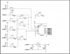
There is a schematic at the very end of the page that i am working with along with a list of parts. I will post these below.;

Now i have already ordered and received all the parts listed in the gear parts list.txt attached to this post.

The issue i am having is making heads or tails of the schematic.

So here are my questions:
1. Everything listed as VCC, what IC should that connect to?
2. What do P1-P8 mean and connect to?
3. Should pin 11 be connected to anything or left unconnected?
4. Should there be a 12v power source on this circuit anywhere or will the power supplied come from the gear shift sensor?

I know that P9-P15 are the outputs for to the 7-seg LED display and the P16 is most likely the ground for the display so that i have figured out.

I have breaded this circuit the best i could figure out and i cant seem to get it working. I can get the display to read 0 and 7 and even that is sporadic at best.

A noob stupid re diagram using an icon of the IC rather than the gates and inverters like this one had would be much more helpful if anyone can read this.

Can anyone please help me with this?
 

Attachments

  • IC_schematic.jpg
    IC_schematic.jpg
    99 KB · Views: 4,503
  • Gear indicator Parts List (1).txt
    750 bytes · Views: 839
So here are my questions:
1. Everything listed as VCC, what IC should that connect to?
2. What do P1-P8 mean and connect to?
3. Should pin 11 be connected to anything or left unconnected?
4. Should there be a 12v power source on this circuit anywhere or will the power supplied come from the gear shift sensor?
1. VCC is the power for the circuits. It is generated by the U3 voltage regulator.

2. P1 through P6 apparently connect to switches internal to the bike that are grounded to indicate the gear position. Not all bikes have those switches.
See reply 4 for the rest of the answer.

3. If you mean pin 11 on U2-D, that's an output and you leave it open

4. 12V from the battery goes to Pin P7 to power the U3 regulator and generate the 5V Vcc voltage. P8 goes to the battery ground (or chassis).
 
Ok bear with me i just threw this one together in MS paint and it is in no means meant to be read easily for the sake of wiring but more so to be easier read for the pin out locations of all the ICs. Do i have everything mapped correctly? If so on the gear connections should that wire connecting to the gear be applying a + voltage or a ground?

I have breaded this schematic and it doesnt seem to work.
 

Attachments

  • circuit.jpg
    circuit.jpg
    94 KB · Views: 1,582
Do you have 5V at Vcc?

The pin diagram is viewing the chips from the top. Is that how you wired them?

Have you double-checked the schematic to the wiring diagram.

Have you used an ohmmeter to verify that all wires in your circuit wiring correspond to the wiring diagram (continuity check)?
 
crutschow thanks for the answers to everything. I tested everything out again and double checked all my wires. They all match the schematics, the issue was the voltage. My battery was only outputting 5v in the VI so only a little over 2v were coming from the VO. Fresh batteries and verified a solid 5v on the VO lit the 7 seg up like a Christmas tree. I started grounding all the gear wires one at a time and it is working good although one problem does still exist. This problem might not be a problem at all once installed or it could be a major problem and a result of a ban circuit design.

When i ground gear 2 (P2) wire or gear 3 (P3) wire the display sticks. IE: ground and remove gear wire 2 the display still reads 2 rather than resetting for 0. Same for the gear 3 wire. Ground, remove display still shows 3. Now to make matters worse if i go from gear 3 wire to gear 1, 4, 5, or 6 wire the display freaks out and displays 7. It doesn't cause an issue when using gear 2 wire for some reason. Now in testing it seems i can touch any wire to the gear 3 wire on removal and it instantly resets to 0 and then i can plug in 1, 4, 5 or 6 and it displays just fine. Maybe i need a diode somewhere for gear 2 and 3 wires??
 
Well, I thought it was curious that P2 and P3 didn't have 1k pullups to Vcc as the other inputs do. Try adding resistors to those and see if that helps.
 
Hey crutschow, I thought the same thing when i first started putting everything together. I ran through diodes trying to block power from bleeding or something and then just decided to drop P2 and P3 in with resistors. Sure enough worked great so the sticking display is rectified on 2 and 3! Everything looks to be in order. I also tested the drain and the highest drain is 0.35A only when P3 is grounded. Everything else sets only a 0.11A-0.01A. I will redo the diagram and post it with a detailed write up including modifications to the sensor to get this system to work.

The sensor modification will be for 99-06 Suzuki GSX600F / GSX750F (Katana 600cc and 750cc) models.

The next step would be putting a 1k pot for a dimmer, maybe using a 555 timer duty circuit inline with a pot would produce the best results here?

Also looking into a photo sensor mod with the pot mod to auto dim the display to a controlled rate at night.

For example run a dimmer for daylight then at night the photosensor kicks in and overrides the daytime pot activating a second pot set for a dimmer setting. I doubt i could run this through the same pot but if so that would be perfect. IE daylight = full bright with pot dimmer for custom brightness during the day and then night time = half value of the pot currently set for daylight. Any thoughts on something like this?
 
Last edited:
Hi,

you might want to have a look at this circuit.

It does not require an internal switch to indicate gears, and uses Hall switches and a permanent magnet attached to the shift lever instead.

It uses an ATtiny25 microprocessor.

The software is set to five gears (default setting), but the source code can easily be modified for six gears.

If you prefer that circuit please PM me your name and email-address.

Boncuk
 

Attachments

  • GEAR-INDICATOR-SCH.gif
    GEAR-INDICATOR-SCH.gif
    21.3 KB · Views: 1,748
  • GEAR-INDICATOR-BRD.gif
    GEAR-INDICATOR-BRD.gif
    29.1 KB · Views: 1,952
Hi,

you might want to have a look at this circuit.

It does not require an internal switch to indicate gears, and uses Hall switches and a permanent magnet attached to the shift lever instead.

It uses an ATtiny25 microprocessor.

The software is set to five gears (default setting), but the source code can easily be modified for six gears.

If you prefer that circuit please PM me your name and email-address.

Boncuk

Hey Boncuk, thanks for the heads up on the circuit. I will stick with the IC boards at the moment. Id rather not dive into anything that requires source code just yet. I plan to eventually move to microprocessors in the very near future though and i will start with a gear indicator design before stepping up to a DIY miles tagger design. Thanks again! I will keep in touch when i am ready to under take this project for sure.
 
Status
Not open for further replies.

New Articles From Microcontroller Tips

Back
Top