Continue to Site

Welcome to our site!

Electro Tech is an online community (with over 170,000 members) who enjoy talking about and building electronic circuits, projects and gadgets. To participate you need to register. Registration is free. Click here to register now.

  • Welcome to our site! Electro Tech is an online community (with over 170,000 members) who enjoy talking about and building electronic circuits, projects and gadgets. To participate you need to register. Registration is free. Click here to register now.

GCSE Project, Need Help

Status
Not open for further replies.

woz_maksie

New Member
Hey all, this is my first post, and i just like to say thanx in advance
Basically im 16 and doing my GCSEs and 1 of them is electronics. Ive got a very good understanding for electronics regarding components and the workings, but after desgining my circuit and producing it, ive found that it does not work as planned

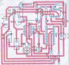
The idea of the circuit, is that it is suppose to put in the soil, of a plant pot. Then, using the op-amp, it compares the soils resistance to the referenced one. If the soil resistance is higher (this means the plant needs water) it feeds into the decade counter, the first output triggers the monostable which turns on a solenoid which controls the water for a set amount of time.

When created in Crocodile clips, my circuit worked, but after i built it, the output on op-amp was in milli volts :? (i cant remember exactly which op-amp it was, but its not a 741)

Can yall find anthing wrong with the circuit or the diagram.

Thanx for your help
 

Attachments

  • my_circuit.jpg
    my_circuit.jpg
    17.1 KB · Views: 314
  • my_circuit_pcb.jpg
    my_circuit_pcb.jpg
    115.1 KB · Views: 499
Are the inputs correct? non-inverting going higher than inverting? It should then send the output to the rail (about 9 volts).

I can not read the small schematic. Can you post a larger one?
 
I can but its quite low quality because its scanned in as i don't have access to the program. If there is something on there that you cant see, i can tell you.

Ive taken the non-inverting input as the Vref and the inverting as the Vin, from the soil resistance. In the exact diagram, the soil resistance is higher than the non inverting so you'll notice that the relay has been triggered, and would have turned on the solenoid, if it were there.

You see it works in the computer simulation, after i made it, the output in around 3mV. Any ideas
 

Attachments

  • my_circuit_enlarged.jpg
    my_circuit_enlarged.jpg
    43.2 KB · Views: 542
I'm guessing you're using a johnson decade counter (4017B type). You've got the second output of the counter feedback to reset itself. This is not good practice because there is no guarranty the second output will maintain its high state to permanently reset the counter.

While in the alligator clip state, the leads may have been long enough to introduce delays so that the minimum reset pulse width is attained. However, on a PCB, the leads are now much shorter that this is no longer the case.

I was just wondering why you had to use the 4017B. What you're trying to achieve is a momentary negative going pulse when the output of the comparator goes low. A one-shot multivibrator can do it better.

Or you can replace the 4017B with a capacitor plus a protective diode in parallel with the resistor at the 555's pin 2 input.
 
1. What are the part numbers of the decade counter and the op amp you used on the PC board?

2. The op amp outputs need to swing almost rail-to-rail (zero to 9 volts) in order to reach the logic levels required by a digital input. The one you are using may not do that. A comparator, such as LM393, would be a better choice, but you can buy rail-to-rail output op amps.

3. You should add some hysteresis (positive feedback) to the comparator (op amp), to ensure clean, fast switching of the output. Try adding a 470k resistor from output to noninverting input.

4. If the counter is a 4017, it has a positive-edge triggered clock. The one in your schematic has a bubble on the clock input, indicating negative-edge triggering. This is consistent with the way your op amp inputs are connected - the output will go low when the soil dries out. However, if you are using a 4017, you need to reverse the inputs on your op amp.

5. I agree with Motion that you don't need the counter. You could ac-couple the output of your comparator directly into pin 2 of the 555. This has the added advantage of not requiring a rail-to-rail swing on the comparator's output. You do still need the hysteresis, but leave the inputs as they are.
 
Sorry but the switch does not control all the power from the 9V battery on the PCB.

The + connection of 9V is going to the IC2 (via R6) directly before the main switch.
 
Without having hysteresis by adding a 470k resistor to the opamp, I think the opamp will oscillate when its inputs reach the switching voltage. The oscillation might not produce a proper digital square-wave output but probably just a low-amplitude triangle-wave. Therefore the counter isn't triggered.
 
Thanx guys, 4 all your help, bt im nt sure i understand y'all exactly
Thanx eblc1388 also, i had that problem with my switch, and never figured what the problem was.

Here is what i uderstand at the moment. PLLZ correct me n explain as evidenty i am wrong

When the inverting input is higher then the non inverting, the output should trigger the decade counter, which will trigger the monostable, and then reset. My exact problem is, even if the resistance of the inverting higher, nothing happens, so i chekd with a multimeter, an found the output is onli mV. Now i would assume this is not enough to trigger the decade counter. Can some1 please tell me y, and sum up what every1 else is saying, because i am not 100% sure what u mean
 
There are many different decade counter ICs available. You haven't told us which one you used, so we are just guessing about how your circuit should work.

The opamp's output should be high when the soil is wet then go low when the soil is dry. Does it?

Your counter should have a circuit to reset it when the power is connected to the circuit. Now it powers-up in any count.
 
sorry, its a 4017 i believe
also, wen the soil is dry, the output should be high, as the resistance will be high, and its fed into the inverting input

now wen the resistance is higher at da inverting, the output on the opamp is VERY low lyk mV

about the decade resetting, should it not reset after a 1 pulse from the op amp?
 
woz_maksie said:
sorry, its a 4017 i believe
also, wen the soil is dry, the output should be high, as the resistance will be high, and its fed into the inverting input

now wen the resistance is higher at da inverting, the output on the opamp is VERY low lyk mV
A clock input for a 4017 needs a positive-going signal. Your opamp's output is the opposite.
Your opamp is operating normally as an inverter, so when the soil gets dry then its inverting input goes higher and its output goes low.
You didn't say which opamp you have for us to see if a few mV at its output is normal.

about the decade resetting, should it not reset after a 1 pulse from the op amp?
It might take 9 pulses. You cannot predict which count its starts with.
All circuits with counters in them should have a few parts added to reset the counter during power-up.
Your circuit doesn't need a counter anyway since the output of the opamp can be capacitor-coupled to the trigger pin of the 555. Add the 470k resistor from the output of the opamp to its non-inverting input to make it switch very quickly.
 
As I said, and Audioguru said, you don't need the counter. See below.
The optional 4.7k resistor maintains hysteresis even if the threshold pot is set very low.
The op amp needs to swing more than 6V peak-to-peak when it switches.
 

Attachments

  • soil_moisture_sensor1.jpg
    soil_moisture_sensor1.jpg
    36 KB · Views: 232
Status
Not open for further replies.

Latest threads

New Articles From Microcontroller Tips

Back
Top