Continue to Site

Welcome to our site!

Electro Tech is an online community (with over 170,000 members) who enjoy talking about and building electronic circuits, projects and gadgets. To participate you need to register. Registration is free. Click here to register now.

  • Welcome to our site! Electro Tech is an online community (with over 170,000 members) who enjoy talking about and building electronic circuits, projects and gadgets. To participate you need to register. Registration is free. Click here to register now.

GCSE project involving PIC....

Status
Not open for further replies.

varkunus

New Member
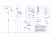
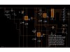
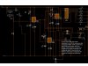
Hello there, I am currently trying to work on my GCSE electronics circuit schematic using the program live wire. I am designing a safe alarm which will when the door is open at certain periods (ie overnight), then in conjunction with a PIC sending out a high pulse (maybe low) a reed switch will trigger a circuit. When the circuit is triggered (hopefully) it will use a monostable to delay before the output of the circuit (siren, lights from decade counter, and a pump to spray smart water). Then the siren, and lights will stay on indefinately, but the motor should go off after 3-5 seconds in order to not burn the motor/pump out. But when i engange both switch (reed and PIC) then the motor will only stay on as long as it takes for the capasitor to charge. I really am stuck, and I am running out of time. If anyone would could help me then that would great :D
 

Attachments

  • Circuit with PIC on main rail.jpg
    Circuit with PIC on main rail.jpg
    64.6 KB · Views: 278
  • Seems to work but only works if i press reed quickly, open it then close it. (before cap is char.jpg
    Seems to work but only works if i press reed quickly, open it then close it. (before cap is char.jpg
    79.7 KB · Views: 196
no no no, the PIC is being uses as clock, and timer which will arm the alarm at night time. So that if the safe door is opened during the day then it will have no effect, but at night when the PIC is active then it will. Anyway any ideas..?
 
no because ive been told the way the mark scheme is done that I need to include conventional components otherwise it just looks like a programming exercise. Still anyway of doing it?
 
The pointlessness of educational projects.

Can't you build anything more interesting like a true RMS or power meter? That way you need to use both conventional components and a PIC.
 
I agree with the instructor on this one. Make them learn more than just uC programming. If it were me, I'd make them do projects with no uC at all until they've mastered the basics. In general, many, if not most, educational projects are pointless other than teaching basic principles.
 
thanks for your controversial discussion guys, but could you please help me with my circuit! It seem capacitor 1 is the problem. Like if i press down the reed switch with a rapid on/off/on then it works with the inverters and switches in parallel. But if the pic switch is down for a period of time and the reed switch is broken, then C1 charges, and from what I can understand when capacitor is fully charge it dis-engages the motor. Our old teacher has left and we have a new teacher who although she is trying her hardest doesn't have the expertise our old one had. So please help!
 
You appear to be running the motor off of the same power rail as everything else. The motor will put a lot of noise into the system. You need to figure out a way to separate the two. Speaker could also cause a problem. No back EMF diode on the motor.

I'm not surprised you are having problems - you are running on ugly power.
 
so what should I do stick a diode in where the motor is running to negative? I really know I shouldnt ask for help but I AM running out of time, so some strong pointers in the right direction would be useful
 
At least you're asking for help, not just expecting us to do it for you.

There needs to be a diode in reverse parallel with the motor to protect the transistor from the high voltage spike produced when the motor is turned off.
 
sorry i havent been taught about reverse parallel could you just put a little ring on the diagram please. And this wont help with the problem of how to turn the motor off once the circuit is trigger. Is there anyway I can stop C1 charging when pic switch engaged but reed switch is not? Then it begins charging when reed switch engaged. Cause if I can do that then I have a working circuit I think.
 
**broken link removed**
 
The pointlessness of educational projects.

Can't you build anything more interesting like a true RMS or power meter? That way you need to use both conventional components and a PIC.

As you're in the UK you should know better, GCSE's are examinations taken at 15/16 years of age - the level of Electronics taught is absolutely minimal, with the teacher often knowing nothing about Electronics at all.

Generally, a teacher will be appointed to teach Electronics, and sent on a two day course - it could be an English teacher or anybody - and they almost certainly have zero Electronics knowledge previous to this.

So all they are able to do is follow the book exactly as they have been taught on the short course, it's really NOT a very good introduction to Electronics.

At the school where my daughter is now in 6th form, I used to know a guy (called John) who went in as a volunteer to teach Electronics and run clubs - now he was a VERY, VERY clever guy. He worked for Lowe Electronics and (amongst other things) designed their high performance HF band receiver.
 
i have done that but it still does not work, so can you help me with the C1 problem

hi,
Looking at the cct, you have a VR1/C1 timing period which can be set <= the timing period of VR2/C2.

As VR2/C2 is only being charged during VR1/C1 which sets Mono1 output high, how can Mono2 reach full charge.??

Why dont you trigger Mono2 with Mono1 rather than trying to control the charge voltage/time.
 
ok here is a new circuit diagram. I have put a capasitor infront of the motor. Now this works providing the PIC switch is closed, and then then reed switch is quickly opening and quickly closed. Is there any way of using a mechanical switch which does this? Or would I have to use a way of doing it. I just want a switch which will go closed, open closed very quickly. Anyway hope you can help I REALLY AM desperate.

richard
 

Attachments

  • Cap infront of motor.jpg
    Cap infront of motor.jpg
    82 KB · Views: 151
ok here is a new circuit diagram. I have put a capasitor infront of the motor. Now this works providing the PIC switch is closed, and then then reed switch is quickly opening and quickly closed. Is there any way of using a mechanical switch which does this? Or would I have to use a way of doing it. I just want a switch which will go closed, open closed very quickly. Anyway hope you can help I REALLY AM desperate.

richard

hi,
You need to 'ac' couple the switch action, look at this image.

Do you follow.?
 

Attachments

  • esp03 Oct. 10.gif
    esp03 Oct. 10.gif
    40.2 KB · Views: 133
ok I didnt really understand that, so what would I need to actually do circuit wise put two resistors in parallel to the circuit. And would I put in on MON1 or mon2? Thanks this has been the most useful post so far!
 
ok I didnt really understand that, so what would I need to actually do circuit wise put two resistors in parallel to the circuit. And would I put in on MON1 or mon2? Thanks this has been the most useful post so far!

hi,
What the Res/Cap on the trigger input does is to 'differentiate' the edges of the switch pulses.

All that means, you push and hold the switch and the cap sends a short low going pulse to the 555 trig input. Release the switch and a high going pulse is created which does nothing.

This is the same as you were doing at first, pushing the switch quick on/off.

Look at the circuit I posted, use a about a 1K0 reslstor at the switch, then the cap and the resistor shown of the circuit.

Make the same circuit between the mono1 output and mono2 trig.

EDIT: Look at this image.
 

Attachments

  • mono1.gif
    mono1.gif
    170 KB · Views: 145
Last edited:
Status
Not open for further replies.

Latest threads

Back
Top