Hi,
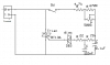
I am designing a dimmer with a triac. It's mentioned in the teriac datasheet that the max gate current is 35mA. I have designed the attached circuit but I don't know how to calculate the gate current. The circuit works properly but I'm not sure it's safe while triggering or not.
Please check the circuit and let me know your opinions.