Acoustic Addict
New Member
Hi Guys,
I just stumbled on your excellent forum & thought I'd post a couple of questions for which I need your expertise & advice.
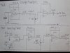
Fig:1
This is charge amplifier circuit driving a small piezo disc.At first I wired a 100k pot in series with the 100 ohm Re. on the output of the buffer stage.It works well until I turn the "pot" nearly to maximum when there's a noticeable change in the tone. Further this wiring does not cut the gain completely either.
I then wired the pot on the output as shown in the diagram. This too works fine until I turn it down the fully when there's a very loud hiss. I also notice that there's a slight variation in the overall tonal characteristics. Replacing the values of the pot to 47k/100k only made the noise/gain either less or more!
Q:
Which configuration is the better or preferable of these two? Am I overlooking something? Why is this behaving this way?
Fig:2
This is a simple two stage summing/mixer circuit.
Q:
Is the value of the pot -47K- is an ok?
Originally, the volume pot was connected in the main the output, but I rewired it this way to reduce noise in the circuit.
I'd be very grateful anyone of you out there can tell me of any design error(s) I might have made & help me to further improve on these circuits.
Cheers!
I just stumbled on your excellent forum & thought I'd post a couple of questions for which I need your expertise & advice.
Fig:1
This is charge amplifier circuit driving a small piezo disc.At first I wired a 100k pot in series with the 100 ohm Re. on the output of the buffer stage.It works well until I turn the "pot" nearly to maximum when there's a noticeable change in the tone. Further this wiring does not cut the gain completely either.
I then wired the pot on the output as shown in the diagram. This too works fine until I turn it down the fully when there's a very loud hiss. I also notice that there's a slight variation in the overall tonal characteristics. Replacing the values of the pot to 47k/100k only made the noise/gain either less or more!
Q:
Which configuration is the better or preferable of these two? Am I overlooking something? Why is this behaving this way?
Fig:2
This is a simple two stage summing/mixer circuit.
Q:
Is the value of the pot -47K- is an ok?
Originally, the volume pot was connected in the main the output, but I rewired it this way to reduce noise in the circuit.
I'd be very grateful anyone of you out there can tell me of any design error(s) I might have made & help me to further improve on these circuits.
Cheers!