Continue to Site

Welcome to our site!

Electro Tech is an online community (with over 170,000 members) who enjoy talking about and building electronic circuits, projects and gadgets. To participate you need to register. Registration is free. Click here to register now.

  • Welcome to our site! Electro Tech is an online community (with over 170,000 members) who enjoy talking about and building electronic circuits, projects and gadgets. To participate you need to register. Registration is free. Click here to register now.

Gain of "two parallel transistor" Vs "a darlington" (?)

Status
Not open for further replies.

Willen

Well-Known Member
Gain of "Two transistors' darlington" Vs "A single darlington" (?)

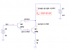
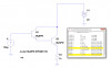
-I can buy a transistor (eg BC547) at very cheap cost. But a darlington (also in TO 92) is very expensive. What happen if I made a darlington connecting two transistors? Does it act equally as a darlington (hFE)?

Lets say I made a darlington using two BC547B (hFE= 350), will it replace to BC517 (NPN darlington)? It would be better if you have hFE calculation.

- I think hFE of two transistor darlington is multiplied for total hFE, isn't it?
 
Last edited:
Yes, a darlington is simply two transistors in one package - you can easily make your own with two transistors (connected emitter to base, and collectors together).

However, what are you wanting a darlington for?, they have specific uses.
 
Series.....It makes the same as a "darlington transistor".

Yes

Yes, series-
1) Both has same collector
2) First's emitter to 2nd's base
3) 1st's base is 'Base' and 2nd's emitter is 'Emitter'

then I don't need to buy such expensive darlington. I can make 350x350 hFE darlington using two 547B.

Everywhere can I use it as a replacement of small (eg BC517, MPSA13) darlington? (if yes wow!)

...However, what are you wanting a darlington for?, they have specific uses.

Not exactly. Just asking for my shoping list and budget :)
 
Can I use a darlington to amplify super tiny level of audio to loud? (like detected (modulated) audio from germanium diode? )
 
Be aware that the first transistor will be operating at a very low collector current (nearly equal to the second transistor's base current) and that can significantly reduce the gain of the first transistor. Thus to determine the gain of the Darlington pair you need to use (or measure) the gain of the first transistor at it low expected current.
 
Can I use a darlington to amplify super tiny level of audio to loud? (like detected (modulated) audio from germanium diode? )
A darlington transistor has high current gain but the same or less voltage gain as a single transistor. It drives a speaker poorly since it will be class-A.
A crystal radio needs a class-AB (or class-D nowadays) power amplifier with a fairly high input resistance and high voltage gain to drive a speaker loudly.
 
Can I use a darlington to amplify super tiny level of audio to loud? (like detected (modulated) audio from germanium diode? )

No, that's not what darlingtons are for - they are really only rarely used, and mostly in power amps etc. to give high gain, high power output stages.
 
darlingtons are most often used in switching applications. darlingtons are much slower than either transistor by itself. this is because the miller capacitance is the B-C capacitance multiplied by the beta. so for a transistor that has an input capacitance of 1pf, and a beta of 350 has a miller capacitance of 350pf. a darlington with two of the same transistor would have a miller capacitance of 122nf. this is why you never see darlingtons used for any RF application.
 
Hi there,


You can create a Darlington transistor yourself that's for sure. The drawback of course is that you have to use two transistor packages instead of one, and you have to supply your own base resistors.

Also, the total gain is not really B1*B2 as is commonly believed, as that is just an approximation. The real combined beta is B=B1*B2+B1+B2+1.

This describes this a little better:
https://hightechavenue.blogspot.com/
 
the formula used in the link is Btot=(B1+1)*(B2+1).

so for a pair of transistors with each having a beta of 100, it would be 101*101=10201 and the approximated calculation of B1*B2 would be low by 2%. as the betas of the individual transistors decreases, the error percentage increases. somewhere along the way, somebody writing a textbook must have said to themselves "if we drop the +1 terms out of the equation, it's close enough"...
 
darlingtons are most often used in switching applications. darlingtons are much slower than either transistor by itself. this is because the miller capacitance is the B-C capacitance multiplied by the beta. so for a transistor that has an input capacitance of 1pf, and a beta of 350 has a miller capacitance of 350pf. a darlington with two of the same transistor would have a miller capacitance of 122nf. this is why you never see darlingtons used for any RF application.
The Miller capacitance is Ccb*(Av+1), where -Av is the voltage gain of the stage. Av has very little relationship to beta.
 
Analog Avenue is (slightly) wrong. Darlington beta (Ic/Ib) is βtotal=β1β2+β1+β2.
See attachment.
 

Attachments

  • Darlington beta annotated.png
    Darlington beta annotated.png
    11.2 KB · Views: 582
Analog Avenue is (slightly) wrong. Darlington beta (Ic/Ib) is βtotal=β1β2+β1+β2.
See attachment.


Hi there Roff,

I see you did not look closely at the diagram in the link :)
If you did, you would have seen that there are two different total beta's, one for the collector and one for the emitter. You quoted the one for the collector only, while "Analog Avenue" quoted both collector AND emitter gains.

As unclejed mentioned too the difference between the exact theoretical calculation and the approximation isnt that much either but it's good to know. Often the second transistor has less gain than the first too, and sometimes it is much less because it is a power transistor.
I did look closely at the diagram in the link. In the left-hand drawing, he had the collector of the first transistor connected to the wrong side of the collector resistor. That circuit is not a true Darlington. It's an emitter follower followed by a common emitter stage.
First, "beta" is defined as Ic/Ib. Ie/Ib has no "official" name, AFAIK. Ie/Ib=beta + 1.
Second, Analog Avenue's equation is βtotalcollector=β1β2+β2. I maintain that it is actually β1β2+β2+β1. No argument that βtotalcollector≈β1β2.
 
Hi Roff,


In the left hand drawing it does not matter where the collector resistor appears because all the analysis is based on current measurements. All the currents are given therefore it works just as indicated. But your observation is still interesting to me because it doesnt *look* exactly like the right hand drawing. In other words, short out that resistor and see the same results.

You are also very correct about the official name for the Ie/Ib quantity, but it is still the gain we find when we trace from the base of the first transistor to the emitter of the second transistor. Your observation is still interesting i think though because it's not normally called 'beta'. However, the diagram is clear on what the gain is.

The Btotalcollector is actually B1*B2+B2, not B1*B2+B2+B1 as you have stated. If you look at the current measurements, you'll see that the output collector current is 110ma, not 120ma. Lets do the math to prove this...
First, the input is 1ma, the gain is 10 so the first collector current is 10ma and the sum is 11ma so we have 11ma at the emitter of the first transistor. That feeds into the second transistor base, and that transistor has a gain of 10 so the collector current is 11ma*10=110ma, and that is clear on the diagram as well. Now lets it with the gains both ways.

Method 1: B1*B2+B2
10*10+10=110, 110*1ma=110ma, exactly as shown in the diagram.

Method 2: B1*B2+B2+B1
10*10+10+10=120, 120*1m=120ma, not the right result.

So which method would you use? Since i get the correct result with method 1 i would use that method and that is the same method as the diagram shows. Also, a simulation shows 110ma not 120ma so i am very convinced that the diagram shows the correct result.

Also, try to calculate the emitter current of the second transistor and try to figure out how it could come out to only 1ma more than the collector current if we did believe that the collector current was 120ma and with the base current of the second transistor being the sum of base current and collector current of the first transistor.
 
Hi Roff,


In the left hand drawing it does not matter where the collector resistor appears because all the analysis is based on current measurements. All the currents are given therefore it works just as indicated. But your observation is still interesting to me because it doesnt *look* exactly like the right hand drawing. In other words, short out that resistor and see the same results.

You are also very correct about the official name for the Ie/Ib quantity, but it is still the gain we find when we trace from the base of the first transistor to the emitter of the second transistor. Your observation is still interesting i think though because it's not normally called 'beta'. However, the diagram is clear on what the gain is.

The Btotalcollector is actually B1*B2+B2, not B1*B2+B2+B1 as you have stated. If you look at the current measurements, you'll see that the output collector current is 110ma, not 120ma. Lets do the math to prove this...
First, the input is 1ma, the gain is 10 so the first collector current is 10ma and the sum is 11ma so we have 11ma at the emitter of the first transistor. That feeds into the second transistor base, and that transistor has a gain of 10 so the collector current is 11ma*10=110ma, and that is clear on the diagram as well. Now lets it with the gains both ways.

Method 1: B1*B2+B2
10*10+10=110, 110*1ma=110ma, exactly as shown in the diagram.
You have not accounted for the collector current of the first transistor. It also flows into the Darlington collector.

Method 2: B1*B2+B2+B1
10*10+10+10=120, 120*1m=120ma, not the right result.
See the attached simulation.

So which method would you use? Since i get the correct result with method 1 i would use that method and that is the same method as the diagram shows. Also, a simulation shows 110ma not 120ma so i am very convinced that the diagram shows the correct result.
I'll bet you probed the current of the 2nd transistor. That does not include the collector current of the 1st transistor.

Also, try to calculate the emitter current of the second transistor and try to figure out how it could come out to only 1ma more than the collector current if we did believe that the collector current was 120ma and with the base current of the second transistor being the sum of base current and collector current of the first transistor.
 

Attachments

  • Darlington beta sim.png
    Darlington beta sim.png
    36.6 KB · Views: 462
Hello again Roff,


Hey that makes a lot more sense now, thanks for pointing that out. So the diagram is correct but it's quite misleading because the second transistor collector current is not the only current that should be considered when calculating what we might normally call the "beta". So i agree that in the real Darlington it should be B1*B2+B1+B2, but also note that the original diagram has the correct currents shown just not the right beta calculated :)

I guess we agree that the gain to the emitter is B1*B2+B1+B2+1 which is verified by your simulation also, but it should not be called 'beta' because it is really beta+1 when beta is the more correct overall Darlington beta.
 
Status
Not open for further replies.

Latest threads

New Articles From Microcontroller Tips

Back
Top