Continue to Site

Welcome to our site!

Electro Tech is an online community (with over 170,000 members) who enjoy talking about and building electronic circuits, projects and gadgets. To participate you need to register. Registration is free. Click here to register now.

  • Welcome to our site! Electro Tech is an online community (with over 170,000 members) who enjoy talking about and building electronic circuits, projects and gadgets. To participate you need to register. Registration is free. Click here to register now.

Gain and amplitude of a LC oscillator with a non ideal OPAMP

Status
Not open for further replies.

d_sl4y3r

New Member
I'm studying for electronics, but I'm lost with this exercise.

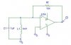
Consider the following oscillator in the picture.

The AMPOP is not ideal: Rin=1k, Rout=1.
How do I determine the minimal voltage gain Av in order for the circuit to function?

Also, the RMS current that feeds the AMPOP is 4mA.
Ignoring the small internal loss of the amplifier, how do I define the oscillation amplitude at the terminals of the LC section?
 

Attachments

  • lc_negimp.jpg
    lc_negimp.jpg
    8.2 KB · Views: 3,009
Hi,

I'm afraid you're a little too vague with your spec's.
What voltage gain are you talking about, are you saying that the amplifier is not a true op amp and that you can set the internal gain, or do you expect to set the gain with the 10k resistor?
Also, what do you mean by "4ma rms feeding the amplifier", where is that exactly?
 
I think the voltage gain in question must be Avmin=A/(1+BA).
And I think the RMS current charge of 4mA is the one going through Rf, but no more detail is given in the problem.

This is really a poor quality OPAMP for exercising purpose.
I suppose the idea is to understand the effect of the intrinsic "imperfection".

Also, I think the OPAMP here is implementing a negative impedance, to compensate for the energy loss of the LC circuit.
This because in reality the LC section behaves as C//L//R, and so the oscillation get smaller and smaller until all the energy has dissipated.

This is a theoretical problem given to me as it is.
I'm trying to solve this as a personal study, but I don't know how to.
 
Hello again,

Well, we can assume a few things and take it from there and im sure you would learn something that way.

Since they say the 4ma "feeds" the op amp, maybe they mean the current going into the non inverting terminal. That would mean we would have to find the voltage gain for the "op amp" that would maintain 4ma into that terminal given the relatively low input impedance of 1k and output R of 1 ohm.

If you want to we can proceed using those assumptions. Is this ok with you then?
If so, we can probably assume the LC is an open circuit at resonance, so the current goes through the series combination of 1 ohm, 10k, and 1k.
 
Last edited:
Hi again MrAl,

Yes, I'm OK with those assumptions.
In that case, how would you define A, B and Avmin?

If LC is an open circuit at resonance, how can we define the voltage V at the terminal of that section?
All I have in mind is v(t)=V*cos(W*t), W=1/sqrt(L*C), f=W/(2*pi).
 
The circuit you have here is essentially a negative impedance converter:

Negative impedance converter - Wikipedia, the free encyclopedia

There are some differences between your circuit and the one on the wikipedia page, but your circuit can still present a negative impedance at the + input terminal.

When they say that Rin = 1k, it's not clear whether they mean this to apply only to the + input, or to both inputs, and whether that is only a common mode impedance, or whether there's some differential mode impedance also.

At any rate, what you must do is add the non-idealities to your model and calculate the input impedance. You will obtain an expression for the input impedance that just becomes negative for some value of Av; that is the value that will sustain oscillations.
 
Hello again,


With the assumption that you need 4ma going into the non inverting terminal and the circuit at resonance and the input impedance from the non inverting terminal to ground being 1k, it's simple to note that the input at the non inverting terminal has to be at 4v because 4/1000=0.004 amps.
Now with 4ma flowing through the 10k and the output resistance 1 ohm, that means we must have across the two 40.004 volts. The sum of 40.004 and 4 is of course 44.004 volts and that would have to appear at the output. With 4 volts on the input and 44.004 volts on the output the gain would have to be
44.004/4 which equals 11.001, so that's the required gain.

Now 44 volts on the output of the op amp means it would have to be a special high voltage op amp, but these theoretical questions sometimes have rather strange values like that. It does seem like a theoretical question because there is no series resistance for the inductor for one thing.

If one or more of the assumptions isnt right then we need more information to proceed. If it is a simple question as it seems then we did it right. Perhaps you can find an answer sheet somewhere so we can check our results. It might also help to know the context in which this question was being asked...ie what was being discussed in class or in the textbook in that chapter.
 
Last edited:
Good morning everyone,

First of all, thank you for your fast answers.
This is material I have access to from a course, the question is likely to have been created by the teacher himself.
I think it's fine to make assumptions, as long as they are explained as the exercise is beeing solved.
This is probably the right answer, as the question was originally made as multiple choice.

I have found the possible answers in my notes:
{1,3,5,7,9,11,13,15,17,None} for the gain
{5.4,5.8,6.0,14.8,2.3,12.1,4.5,7.3,10.5,None} for the voltage at LC terminals
 
Status
Not open for further replies.

New Articles From Microcontroller Tips

Back
Top