Continue to Site

Welcome to our site!

Electro Tech is an online community (with over 170,000 members) who enjoy talking about and building electronic circuits, projects and gadgets. To participate you need to register. Registration is free. Click here to register now.

  • Welcome to our site! Electro Tech is an online community (with over 170,000 members) who enjoy talking about and building electronic circuits, projects and gadgets. To participate you need to register. Registration is free. Click here to register now.

FX lightsaber circuit modification

Status
Not open for further replies.

Montagar

New Member
Hi all,

I have a few of these FX lightsabers that I would like to use as wall displays. The problem is that the circuit has a 2 minute auto shutoff if none of the movement sensors are activated.

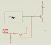
I can not simply bypass the sensors because the processor chip requires on/off "chatter" from the sensors to keep it from executing an auto shutoff.

So my idea is to create some kind of a "pulse" circuit to close and open one of the processor sensor inputs every minute or so.

The circuit runs on 4.5V and it appears that the sensor input on the processor chip is either open or gets 3.7V

The solution needs to be as small as possible because it needs to fit inside the saber hilt with the original circuit board.

I am really not sure what direction to go in and was hoping that someone here could give me some help... thanks!
 
Last edited:
Just to be clear, I am not asking for someone to spoon feed me the solution, all I am asking for is some direction so that I am not "re-inventing the wheel" unnecessarily. :)

Thanks
 
Here is the part of the circuit that I am dealing with.

**broken link removed**

The sensor is not actually a mercury switch, but a ball bearing tilt switch (I couldn't find a symbol for it).
 
Last edited:
A 555 timer circuit was my first thought, but I wanted to make sure that I wasn't missing something simple.

I tried holding that input high permanently but it didn't work because that chip (unfortunately I have no way of knowing what chip it is because it's sealed), only reacts to single high, low, high changes. If held high or low the auto shutoff will kick in.
 
I suspect you're looking at this the wrong way? (which is why I asked for a full diagram).

I would suspect the chip doesn't turn the light ON, rather it turns it OFF - so with a full circuit it's probably easy to just bypass it.
 
I see what you are saying but the LEDs are turned on and off sequentially by the chip. There are 6 "banks" of 10 LEDs each that are connected to 6 different pins on the chip (single simplified diagram):

**broken link removed**

Granted I could bypass the chip completely and just have the LEDs all turn on and off at once but not only is that not as "cool" there is also audio output from the chip as well that needs to stay on. If I can "emulate" the sensor activation I retain all of the these effects.
 
How about If we add a PNP transistor(see the schematic).

When ever the Controller tries to turn the LEDs off, it receives a logic High signal from the transistor, When the Leds are on, It gives a Logic low level
 

Attachments

  • sol2.JPG
    sol2.JPG
    10.6 KB · Views: 346
I dont have a light saber at home but sorry if this is a silly answer to your question,
Are you using a dc supply? why now just try connecting the supply directly to the LED? bypassing all the chips and ICs? just remember to put a resistor to limit the current
 
yuchween said:
I dont have a light saber at home but sorry if this is a silly answer to your question,
Are you using a dc supply? why now just try connecting the supply directly to the LED? bypassing all the chips and ICs? just remember to put a resistor to limit the current
Yes that could be done, but as I mentioned at the end of my last post, there is audio and the sequential LED start up and shut down to take into consideration.

At this point I have solved my problem with a simple 555 timer circuit (pretty much what I was going to use from the beginning, but I thought I would check on my thinking :)).

I just finished testing it and it works perfectly. The 555 timer emulates a sensor "firing" every 90 seconds, thereby keeping the auto shutdown from occurring.

Thanks to all that responded!!
 
Montagar said:
Yes that could be done, but as I mentioned at the end of my last post, there is audio and the sequential LED start up and shut down to take into consideration.

At this point I have solved my problem with a simple 555 timer circuit (pretty much what I was going to use from the beginning, but I thought I would check on my thinking :)).

I just finished testing it and it works perfectly. The 555 timer emulates a sensor "firing" every 90 seconds, thereby keeping the auto shutdown from occurring.

Thanks to all that responded!!

Good job! I know you've already got this working, but I just thought I'd toss a passing idea into the mix just for giggles.

I would try a flashing LED between the movement sensor and the chip (after jumping the sensor), in the hopes that it would trigger the chip when it flashed and fool it. If that didn't work, something like **broken link removed** could be altered to trigger the chip (instead of the standard LEDs).

Might be easier/cheaper than using 555s if you have to make a bunch of these. Downside: it probably uses more current, which might be an issue if you're running on batteries--but I'd think the current use of the device would be dominated by the display lights and sound effects.

I have no idea if this would work but if I had one of those things I'd at least try it. Probably Nigel or one of the other gurus around here could just tell you if it would. I don't have any flashing LEDs around at the moment or I'd test it.


Torben
 
Cry_Wolf said:
WOW ............. Excellent Idea

I hope it should work

It seems to me that it would work and perhaps be a nifty hack. However, I just looked up the price on flashing LEDs, and if what I'm seeing is true, it looks like they run about $2.90 CDN for 1 flashing LED. Given that a 555 costs $0.45 from the same shop, I don't think the flashing LED is going to save any money. Might be worth it if space was at a premium though, unless you went with a surface mount 555.

Oh well.


Torben
 
Am I the only one who can't see either the origional diagram or the flashing LED solution?

There dervers hosting the pictures must be down, to prevent thsi from happening in future, please uploqd the attachments to this site rather thn posting links.

It sounds like you've been ripped off with that flashing LED. Craplins (our equivalent of Radiosh@g) are probably one of the more expensive suppliers in the UK and they sell flashing LEDs for 59p and 555s are only slightly cheaper at 53p.

**broken link removed**

**broken link removed**
 
Hero999 said:
It sounds like you've been ripped off with that flashing LED. Craplins (our equivalent of Radiosh@g) are probably one of the more expensive suppliers in the UK and they sell flashing LEDs for 59p and 555s are only slightly cheaper at 53p.

**broken link removed**

**broken link removed**


Well, I haven't been ripped off yet--haven't bought any. :) I just grabbed that number from an online catalog from a Vancouver shop. I'll be sure to grab some if I can find them at a good price, though.


Torben
 
Status
Not open for further replies.

New Articles From Microcontroller Tips

Back
Top