Continue to Site

Welcome to our site!

Electro Tech is an online community (with over 170,000 members) who enjoy talking about and building electronic circuits, projects and gadgets. To participate you need to register. Registration is free. Click here to register now.

  • Welcome to our site! Electro Tech is an online community (with over 170,000 members) who enjoy talking about and building electronic circuits, projects and gadgets. To participate you need to register. Registration is free. Click here to register now.

Futaba Display

Status
Not open for further replies.

jwb

New Member
While browsing a box with "old stuff" I came across two interesting futaba displays with which I want to do something.

I bought these displays about 20 years ago as read-out for an audio equalizer.

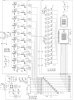
On the site of futaba this display can't be found anymore, and my hope is that someone here knows these displays and can tell me the pin configuration and operating specs (power requirements).

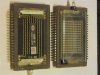
Futaba DM-4 2C (DM-4.5)
14 columns of 10 "dots"
 
Pictures? Preferably good ones ;)
 
I've made a photo of the displays in question :
 

Attachments

  • IMG_2093.JPG
    IMG_2093.JPG
    74 KB · Views: 948
@nigel

Yes, I know they are VFD's but what I'm looking for is the pin configuration and operating specs (power requirements).
 
that's oldschool coolness!! isn't that pretty much the same technology as the nixie watches??
 
@nigel

Yes, I know they are VFD's but what I'm looking for is the pin configuration and operating specs (power requirements).

Essentially you require high voltages, probably between 100V and 200V, with drive transistors rated accordingly. You also need a fully isolated heater voltage for it to work, probably 3V or so?.

For such an old device you may have to experiment to find the connections, but the heater is easily found with a multimeter on ohms, apply a suitable heater voltage, then apply 100V DC to the different pins and find which ones make different segments light up.

It's really a fairly complicated device to drive, due to the high voltages and drive requirements. If you can find an old VCR that uses a VFD you may be lucky and it uses a TDK PSU for powering it, these look like an oversized IF transformer. If you're unlucky, it will be fed from special windings on the main PSU.
 
Hi JWB,

First you have to find out where the filament is.
Take your multimeter, a cup of coffee and a box
of chocolate biscuits and start testing.
You should have a reading between 5 and 20 ohms.
Then you apply a voltage to these terminals, start
with 3 volt, AC or DC is of no importance at this
stage. Look at the display, the filaments, the seven (?)
horizontal lines accross the display, should NOT glow.
If they are not visible, increase the filament voltage
to 5 volt. If they are still not visible the filament
voltage is probably right. I measured 5 volt/300mA.
However all other displays I measured were 3 volt types.
With one exception, a small five digit display which
seemed to be happy with only 1,5 volt/200 mA.
These vfd's have direct heated cathodes which means
that the filament is also the cathode.
Connect the negative terminal of a 12 volt power supply to one
of the filament connections and connect two wires with
alligator clips to the positive terminal of the power supply.
Connect these test leads "somewhere" on the display and move
them around and observe what happens. You might get some
faint glows but continue until you get a segment that glows
bright. One of the two connections is a grid, now you only
have to determine which one. Start moving one test lead
from one connection to another and observe the display.
If you can light different segments of a digit these are
the anodes. If you can light the same segment in different
digits then you have found the grids . . . .
If you are going to use this displays remember that it is
a multiplexed display and 12 volts will certainly be too
low to get a bright display, therefore you will have to
increase the supply voltage to . . . . something between
30 and 40 volt (50 volt is the maximum anode to cathode voltage).
This voltage will depend on the size of the characters and the
number of grids, your guess is as good as any.
Another important detail is the filament voltage.
The cathodes are directly heated therefore there will be
a voltage drop accross the filament/cathode and all digits
will have a different anode to cathode voltage and therefore
a different brightness. You can overcome this problem by
using an AC voltage for the filament. A center tapped
transformer would be ideal but not strictly necessary.
I tested several displays, the one from the CD player has
only 6 grids. REPEAT 1, TITLE, CH and the segments of the
two large digits below are addressed by grid 2, everything
to the left is addressed by grid 1 . . .
The second 11 digit display has 11 grids, I only tested
a few digits and segments to confirm what I already knew
because the grids are clearly visible and they look like
grids too.
Check also the Futaba site for datasheets and application notes.


Futaba Corporation of America

Have much fun ! :D

on1aag.
 

Attachments

  • CD display.JPG
    CD display.JPG
    29.6 KB · Views: 763
  • 11 digit display.JPG
    11 digit display.JPG
    28.4 KB · Views: 786
Futaba Analyzer display

I have got a full working schematic for this futaba DM-4Z display.
You don't need hundreds of volts to drive this VFD.
All you need is +15 & -15VDC.
It's all described and worked out..... awesome circuit.

Email me and I will send you the scans.

fretto1 at gmail.com
 
Essentially you require high voltages, probably between 100V and 200V, with drive transistors rated accordingly. You also need a fully isolated heater voltage for it to work, probably 3V or so?.

For such an old device you may have to experiment to find the connections, but the heater is easily found with a multimeter on ohms, apply a suitable heater voltage, then apply 100V DC to the different pins and find which ones make different segments light up.

It's really a fairly complicated device to drive, due to the high voltages and drive requirements. If you can find an old VCR that uses a VFD you may be lucky and it uses a TDK PSU for powering it, these look like an oversized IF transformer. If you're unlucky, it will be fed from special windings on the main PSU.

I don't quite think they will need 100+VDC, I have used plenty of these on +20VDC, with about 3v for the filament. The anode segments get +/-20VDC and then you apply GND to the grid you want and a certain segment will light up.
Usually the filament is the 2 pins on the ends of the display. I might post picture of one of these hooked up for you if you want :)

-Ben

Edit: oops i just realized this is an older thread...
 
Last edited:
Futaba DM-4 VFD

Ok peoples........

The attached picture should give you all the answers you've asked for.
Again, you do not need hundreds of volts; just -15 and +15VDC.

This is a schematic from an audio spectrum analyzer and it works great.

Hey, in return........ where can I buy one of these?
These displays are AWESOME!!!!!!!!!!!

Anyway.... have fun!!:D


P.S.> ya it's an older thread but ALWAYS appreciated!!!
 

Attachments

  • Futaba DM-4Z.jpg
    Futaba DM-4Z.jpg
    454.9 KB · Views: 1,396
Last edited:
Ok peoples........

The attached picture should give you all the answers you've asked for.
Again, you do not need hundreds of volts; just -15 and +15VDC.

This is a schematic from an audio spectrum analyzer and it works great.

Hey, in return........ where can I buy one of these?
These displays are AWESOME!!!!!!!!!!!

Anyway.... have fun!!:D


P.S.> ya it's an older thread but ALWAYS appreciated!!!

I am not sure where to buy these but maybe check ebay, or take some VCRs or DVD players apart and see if they have one of them inside.

-Ben
 
Status
Not open for further replies.

New Articles From Microcontroller Tips

Back
Top