Continue to Site

Welcome to our site!

Electro Tech is an online community (with over 170,000 members) who enjoy talking about and building electronic circuits, projects and gadgets. To participate you need to register. Registration is free. Click here to register now.

  • Welcome to our site! Electro Tech is an online community (with over 170,000 members) who enjoy talking about and building electronic circuits, projects and gadgets. To participate you need to register. Registration is free. Click here to register now.

Frequency to voltage...

Status
Not open for further replies.

Ian Rogers

User Extraordinaire
Forum Supporter
Most Helpful Member
I sure one or two of you will know the answer, but as I don't do SMT very often ( mainly because I can't see it ) I'm hoping it'll be something simple..

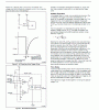
I have three Anemometers I need to repair... One was easy.. Crack in PCB (sorted )... The second had a mechanical issue on the chopper wheel ( glued and sorted )... The third has a component fault... I'm pretty sure that a 555 has done a bunk, but as I said.. Tight circuit and SMT.... The chopper ( IR led / receiver combo ) is working... The buffer opamp is also working.. This op amp is supposed to fire the 555 monostable via a small 1nf cap.. But!! On the scope at this point there is the most feeble pulse that cannot drive the trigger... But the trigger has a flyback diode to 2.5v( sorry that's the positive..Its actually Vcc - 2,5v.... ie.. 21.5 ~ 24 v ) Anywho.. There is also a 47k pullup and another decoupling cap that I'm sure is to the 2.5v... The problem is the 555 isn't triggering... If I trigger it manually ie.. short pin1 and pin 2... It works as expected... So I don't fancy taking the tiny 555 off and replacing unless absolutely necessary..

My gut feeling is there is something up with the impedance on the trigger pin, which is keeping it high... I cant see anything else causing it.. I have removed the diode and the caps ( tough going ), tested them out of circuit...

Anyone else think its the 555 IC???
 
Last edited:
hi Ian,
The Vsup max for a 555 TTL is only 18V, did you say you have 24v.??

E
 

Attachments

  • 555an.pdf
    355.8 KB · Views: 156
  • AAesp01.gif
    AAesp01.gif
    69.8 KB · Views: 151
No! Its only bootstrapped to the Vcc rail.. this can be 18~36v after its converted there is another dual op amp that generates the 4~20mA....

The 555 and the two op amps only see a Vsup of 2.5v ~ 3.0v... I have decided to rip the working one apart and compare the voltages to and from the 555.... If I have to replace it I'll meander down to my local PCB shop and see if they will replace it...

I have tried to recreate the circuit, but it might not be entirely accurate...

circuit.png


Remember the components may not be correct
 
No! Its only bootstrapped to the Vcc rail.. this can be 18~36v after its converted there is another dual op amp that generates the 4~20mA....

The 555 and the two op amps only see a Vsup of 2.5v ~ 3.0v... I have decided to rip the working one apart and compare the voltages to and from the 555.... If I have to replace it I'll meander down to my local PCB shop and see if they will replace it...

I have tried to recreate the circuit, but it might not be entirely accurate...

View attachment 90927


Remember the components may not be correct

The lower VCC spec for a 555 is 4.5V; although, some may work to 3.0 volts (Source: AN170).

John
 
In that case, the CMOS version will operate from 2 to 18 V. Any chance someone replaced it with the wrong one?
I don't think so.. The TLC555 is a CMOS 555 so it fits the bill.... The second op amp should have a cap between the two resistors to ground , low pass filter... I'm just going to try a new 555 as I can't for the life of me see anything untoward on the discreet side... As I said .. diode is ok, cap seems ok...

I hate analogue electronics...... Give me a programming algorithm any day!!!
 
Last edited:
moty22 I believe the power pins are reversed on that chip vs. a 555. You might be interested in checking out High Tech Chips (HTC), which years ago duplicated many 555 functions with 12Fxxx chips.

John
 
moty22 I believe the power pins are reversed on that chip vs. a 555. You might be interested in checking out High Tech Chips (HTC), which years ago duplicated many 555 functions with 12Fxxx chips.

John
I'm quite sure that tomorrow morning Ian will try our suggestions even before having his breakfast.
 
hi Ian.
I would agree with John, IMO at 2.5Vsup the bog standard 555 TTL is being powered below the bottom limit spec' of 4.5V.
Its past correct operation was probably only just marginal at 2.5V, with ageing etc, its now failing.

Is that 1n0 really across the clamp diode.?

E
You could try adding another 1n0 across the existing 1n0 from the OPA drive, give the 555 a bigger pulse
 

Ah! yes... Unfortunately, as it has such a small footprint i wouldn't be able to re-route the power rails... a small pic like the 12f675 would fit, but there is no room to "hang" it anywhere.... Space is very tight.. there is a chopper wheel sandwiched between the two PCB's ... both less than 1" diameter and about 5~7mm between them.... My 52 year old eyes are having a problem.... Even the tiny diode was hard to solder back on!!!
 
Looking at the 555 emulator.... If I tweak the pins and place it upside down the Vcc and Vee pins will be okay
8-SOIC.jpg


This means RA4 and RA5 are potentially pins 6&7 and as they are tied in a monostable I have an ADC on RA4
I have a ADC on (now) pin 2 for the trigger....

Seems like the pic12f1822 is a drop in replacement after all... I have a couple of these so I'll give it a go.

One thing is for sure.... The next guy will get a shock when he opens it up...

I can even ditch the coupling cap as I can generate a pulse on (now pin 3) whenever I want...

Cheers moty22
 
Flipping will put Pin4 (!MCLR, RA3) in the position of Pin5(RA2). RA3 does not have an ADC, so will this part of the code then be a problem:
upload_2015-2-21_7-46-25.png


I can't read C, but it is hard to see how you could truly emulate an NE555/LM555 without having Pin5 (Control) read as an analog input. I have joked many time about using a 12Fxxx (or 12F1xxx) to emulate the NE555 for people wanting FYP's, but that is mostly as a parlor trick. If you simply flip the PIC on its back, I suspect you may still have to physically swap some pins.

In the real situation you describe, I think the low voltage you are seeing could be a result of a problem further upstream. Or, if it was designed that way and simply worked on the fringes of the NE555's capability for awhile, then substitution with a CMOS version might be a more practical solution.

I would rule out an upstream problem first.

John
 
I'm not going to... I'm going to watch the other one that works on a scope and mimic the output..

Pretty sure a pic can read a pulse on the trigger and output a pulse for specific time... I'm not even going to pay attention to pin 4 and 5...
 
Status
Not open for further replies.

New Articles From Microcontroller Tips

Back
Top