Electro Tech is an online community (with over 170,000 members) who enjoy talking about and building electronic circuits, projects and gadgets. To participate you need to register. Registration is free. Click here to register now.
Welcome to our site! Electro Tech is an online community (with over 170,000 members) who enjoy talking about and building electronic circuits, projects and gadgets. To participate you need to register. Registration is free. Click here to register now.
Your request is vague and imprecise. A phase locked loop may be what you are looking for but without knowing what you want to do it is difficult to say. In VHF and UHF communications it is not uncommon to do this kind of thing, although not by a factor of 100 in one step. Is the number 100 important or is it just an example. Try writng a short paragraph about what you want to do, otherwise it will be difficult to help you.
Yes, it's far too vague for any sensible answer - but as Papabravo says, you're probably looking at a PLL design. Although, depending EXACTLY what you're trying to do, a number of analogue multiplier stages 'may' do it?.
(But from your previous posts I seriously doubt it!).
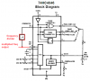
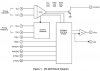
For Cmos logic circuits, I look at the many examples in Don Lancaster's book, "Cmos Cookbook". The datasheets for a CD4046 and a 74HC4046 are also good.
What about the Phase Comparator I, II & III? Which should i used? The input frequency is feed to Pin 14? I have to use two divide-by-10 counter? What is the use of Pin 9 VCO in and Pin 10 Demodulator out?
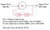
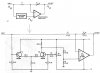
If the triangle wave is perfect and has exactly the correct amplitude and DC level, then the distortion from the XR2206 sine-wave is about 1% at low frequencies.
I haven't tried the Waveform Shaper circuit. It looks like the results will depend on the amplitude of the triangle wave, its DC level, the supply voltage stability and on the temperature.
If the triangle wave is perfect and has exactly the correct amplitude and DC level, then the distortion from the XR2206 sine-wave is about 1% at low frequencies.
This site uses cookies to help personalise content, tailor your experience and to keep you logged in if you register.
By continuing to use this site, you are consenting to our use of cookies.