I'm currently trying to build an analog circuit that will phase shift sine waves of various frequency (from 900Hz to 1100Hz) in a very specific way. What I'm trying to achieve is a constant time delay at the output (in respect to the input) of the circuit without modifying the amplitude of the sine waves. More specifically, here's what I want:
Input/Output:
- Waveform: Sine Wave
- Voltage: 0.1V - 5V
- Frequency: 900Hz - 1100Hz
Output:
- Time Delay: 0.25ms
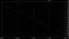
The time delay of 0.25ms suggests a phase shift of:
- 81 deg for 900Hz
- ...
- 90 deg for 1000Hz
- ...
- 99 deg for 1100Hz
I've talked with many profs in my department about this, but unfortunatly since I'm a physics student, none of them has a lot of experience in electronics. Fortunatly, I found this forum and I know at least one of you is smart enough to help me with what I want...
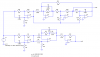
Any design ideas or schematics would be greatly appreciated...
Thanks
SmD
Input/Output:
- Waveform: Sine Wave
- Voltage: 0.1V - 5V
- Frequency: 900Hz - 1100Hz
Output:
- Time Delay: 0.25ms
The time delay of 0.25ms suggests a phase shift of:
- 81 deg for 900Hz
- ...
- 90 deg for 1000Hz
- ...
- 99 deg for 1100Hz
I've talked with many profs in my department about this, but unfortunatly since I'm a physics student, none of them has a lot of experience in electronics. Fortunatly, I found this forum and I know at least one of you is smart enough to help me with what I want...
Any design ideas or schematics would be greatly appreciated...
Thanks
SmD
")