Continue to Site

Welcome to our site!

Electro Tech is an online community (with over 170,000 members) who enjoy talking about and building electronic circuits, projects and gadgets. To participate you need to register. Registration is free. Click here to register now.

  • Welcome to our site! Electro Tech is an online community (with over 170,000 members) who enjoy talking about and building electronic circuits, projects and gadgets. To participate you need to register. Registration is free. Click here to register now.

Fox and Hound cable tracer.

Status
Not open for further replies.

wendelspanswick

New Member
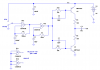
Hi, I found this circuit for a Fox and Hound cable tracer that used a 4001 as an audio generator for the Fox part of the circuit but when I simulated it in both Multisim and Livewire I couldn't get an output on the oscilliscope.
I used a 0.1uf capacitor for u1 and a 0.47uf capacitor for u47 but couldn't get the top right hand gate of the 4001 to oscillate. Anyone care to suggest why it wouldn't simulate?
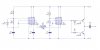
Instead I have used two 555 timers for the oscillation and that works on the sim.
Here's the link to the original circuit. **broken link removed**
 

Attachments

  • 555 fox circuit.JPG
    555 fox circuit.JPG
    25.6 KB · Views: 2,077
  • foxgen.gif
    foxgen.gif
    5.1 KB · Views: 1,985
Last edited:
This is my first post, I was hoping someone could cast an eye over the 4001 circuit to see if it looks like it should work before I go ahead and assemble it. I know it didn't work when I simulated it in Multisim, how accurate are the simulator programs?
Anyone?
 
For one thing, those resistors on the base seem huge, 1k sounds more like it. Maybe a typo?

I was looking at the second schematic, first one has 1k.
 
Last edited:
This is my first post, I was hoping someone could cast an eye over the 4001 circuit to see if it looks like it should work before I go ahead and assemble it. I know it didn't work when I simulated it in Multisim, how accurate are the simulator programs?
Anyone?
I got it to simulate with some changes, but there is no guarantee that the cross-coupled multivibrator will always oscillate, and the other oscillator isn't the best either. See Fairchild AN-118.
If I were building this, I would do it as below. It's much simpler, and is guaranteed to run. I simulated it. You might want to tweak the resistor and/or capacitor values to get the sound you want.
 

Attachments

  • Fox shc.PNG
    Fox shc.PNG
    23.5 KB · Views: 1,766
Thanks for that guys, I think I will breadboard up the circuits and see which one performs the best before I make a PCB.
Thanks again.
John
 
Status
Not open for further replies.

New Articles From Microcontroller Tips

Back
Top