Continue to Site

Welcome to our site!

Electro Tech is an online community (with over 170,000 members) who enjoy talking about and building electronic circuits, projects and gadgets. To participate you need to register. Registration is free. Click here to register now.

  • Welcome to our site! Electro Tech is an online community (with over 170,000 members) who enjoy talking about and building electronic circuits, projects and gadgets. To participate you need to register. Registration is free. Click here to register now.

For FM antennas, should you get a beep when testing for continuity?

Status
Not open for further replies.

sram

Member
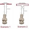
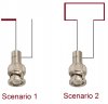
And if you use an ohmmeter across the antenna, will you see the 50/75 ohms that you are supposed to get?

Some meters will beep if the resistance is less than 50 ohms, so that's kinda of misleading.....right? Good meters should only beep if the resistance is close to ZERO (short circuit).......am I right? Or is it just a matter of design?

I want to do some testing for an antenna I'm using to make sure it is fine and built correctly.

Thanks.
 
Last edited:
Antennas will not read at DC the same as at the frequency they are built to work at (AC). Your ohm meter measures at DC. It may read near 0 or near open. Will not read 50 ohms.
 
Oh yeah you are right. Impedance is a function of frequency. But, what does it depend on while on DC? Zero and open are the two extremes you know. If you remember the FM antenna in my other thread, that didn't beep, so it was either open loop or it had some DC resistance.
 
Antenna 1. A wire goes to the left and ends. A wire goes to the right and ends. OPEN
Antenna 1. A loop of wire that at DC is a short. SHORT
 
Antenna 1. A wire goes to the left and ends. A wire goes to the right and ends. OPEN
Antenna 1. A loop of wire that at DC is a short. SHORT

Something like this:


I've drawn the two cases you explained. So, is that right? I'm interested in knowing where does the two leads actually connects/ends. Something is off in the photo I attached I know.
 

Attachments

  • Antenna scenarios.jpg
    Antenna scenarios.jpg
    138.6 KB · Views: 466
Last edited:
How is your radio station?


Still kicking it. I built it and left the location. Hopefully the guys I left there will be able to maintain it. I wonder if wind/rain will cause some trouble to it.

Thanks.
 
Last edited:
Something like this:


I've drawn the two cases you explained. So, is that right? I'm interested in knowing where does the two leads actually connects/ends. Something is off in the photo I attached I know.


ok just completed your drawings for you :)
should make it a little clearer

cheers
Dave
 

Attachments

  • Antenna conns.jpg
    Antenna conns.jpg
    96.3 KB · Views: 2,078
Thanks man. But, it will be great to add an explanation to what you have drawn.

haha ok but not too much else to tell wonder if there was something specific that you would like me to address ?

They are the 2 standard types of dipoles. Both can be used stand alone as you see them or they can be incoprorated into a yagi antenna with a reflector element and any number of director elements.

When in stand alone use the 2 dipoles have the feedpoint impedances as I have shown on the diagram.
When they are incorporated into a yagi system their impedance will drop... the 75 Ohm dipole can drop as low as 25 Ohms, the folded dipole can drop from 300 Ohms down as low as 200 Ohms.
This actually makes the folded dipole very popular for yagi users as its quite easy to make a 4 : 1 BALUN to match the 200 Ohm feedpoint to 50 Ohm coax cable. A number of my yagi antennas have used this method over the years. You will find that many users of the plain 75 Ohm dipole will use 50 Ohm coax to feed it. The resulting mismatch and return loss isnt really a problem. say for a good match of a near 1 : 1 SWR ( near 0W reflected power) when using a 75 Ohm feed point, cable and transmitter. Using a 50 Ohm transmitter and cable to a 75 Ohm feedpoint may result in a ~ 1.2 - 1.3 : 1 SWR. Thats no major problem unless using very hi power transmitters say greater than 500 W where you could end up with several watts of reflected power.
Even then circulators in the transmission line will take care of that reflected power by dumping it to a dummy load and the transmitter will never see it at its output port.

cheers
Dave
 
Last edited:
davenn said:
The resulting mismatch and return loss isnt really a problem.
What about as a receiving antenna? How does that mismatch effect sensitivity and received signal strength? Just curious as I've always wondered how much signal you lose from a mismatch relative to cable length for something like an outdoor antenna.
 
Last edited:
What about as a receiving antenna? How does that mismatch effect sensitivity and received signal strength? Just curious as I've always wondered how much signal you lose from a mismatch relative to cable length for something like an outdoor antenna.

I have never done any specific quantitative experiments.
The closest would be when using say my endfed longwire antenna on any HF freq ... 3 - 30MHz. Although it works and picks up signals right across that range. If I have an antenna tuner inline and resonate the antenna to a given freq, yes the signal strength on the "S" meter will improve quite a few points.
That is probably an extreme case, going from a signif. mismatch to a good match. You will hear the background noise increase substantially as the antenna comes into resonance.
Also of course we are dealing with an antenna that is well out of resonance rather than dealing with a resonant antenna but a mismatched feedpoint as commented on below

But back to a dipole for say 88 - 108 MHz FM band. I suspect that when the antenna is already cut and resonant at the freq of interest, its going to be a signif. mismatch at the feedpoint before it has an obvious effect on a received signal.
Maybe thats a project experiment I should tackle one day. Putting an antenna on the spectrum analyser and then vary the feedpoint matching and see what happens to the signal strength on the analyser :)

cheers
Dave
 
Last edited:
I look forward to anything you'd care to post on the matter, I'd take it as a kindness if you'd private message me a link to the thread of any significantly technical post you make that's new as I don't catch all the new threads here.
 
I look forward to anything you'd care to post on the matter, I'd take it as a kindness if you'd private message me a link to the thread of any significantly technical post you make that's new as I don't catch all the new threads here.

Ahhhh a challenge :) I will do so as time permits and report back

cheers
Dave
 
The folded dipole very popular for yagi users as its quite easy to make a 4 : 1 BALUN to match the 200 Ohm feedpoint to 50 Ohm coax cable.

How can I make such balun easily? My TV has a BALUN labled by ''75/300 ohm'', is it 4:1 BalUn?
 
For a folded dipole Yagi ? yup sure really easy


drawing of 4:1 balun using an electrical 1/2 wavelength of coax

View attachment 64900

Actual pic of same BALUN

View attachment 64901

formula for working out the 1/2 wave length of coax is L (mm) = 150 / freq in MHz x vf (velocity factor of the cable)

so an example for 100MHz is 150 / 100 = 150 x 0.66 = 99mm

so 99mm = an electrical 1/2 wave at 100MHz in a cable with a velocity factor of 0.66

cheers
Dave
 
Last edited:
For a folded dipole Yagi ? yup sure really easy


drawing of 4:1 balun using an electrical 1/2 wavelength of coax

View attachment 64900

Actual pic of same BALUN

View attachment 64901

formula for working out the 1/2 wave length of coax is L (mm) = 150 / freq in MHz x vf (velocity factor of the cable)

so an example for 100MHz is 150 / 100 = 150 x 0.66 = 99mm

so 99mm = an electrical 1/2 wave at 100MHz in a cable with a velocity factor of 0.66

cheers
Dave

But in this figure, shild wire of coax is not connected to antenna pole. Then how does it work well? I think, it works as a transformer becose it is a transformer, isn't it?
 
Removed my redundant reply
Unable to find way to totally delete my old post.
 
Last edited:
what?
 
Last edited:
Status
Not open for further replies.

Latest threads

New Articles From Microcontroller Tips

Back
Top