Electro Tech is an online community (with over 170,000 members) who enjoy talking about and building electronic circuits, projects and gadgets. To participate you need to register. Registration is free. Click here to register now.
Welcome to our site! Electro Tech is an online community (with over 170,000 members) who enjoy talking about and building electronic circuits, projects and gadgets. To participate you need to register. Registration is free. Click here to register now.
I am new to the forum, so hello to one and all and I shall start by stating that I am awful at Electronics (or the Black Art), but like Melchead, I am building a foam cutter and saw the exact same plans online.
I bought the bits today, although I struggled to find a 25Vac Trans so I got a 15vac will this significantly change the values I should use for the other components? or will it be the same?
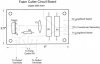
I also have a bit of an idiot question I have just purchased a Teletron T-1502 Transormer and opened the box expecting to find a wiring diagram in the box. There isn't one, so would it be possible for you to answer this question:
If I wish to wire it for 230Vac and get +15v out of it which terminals do I use
The ones on the top would be for 15V, but you need 2 diodes to get DC, if thats what you want.
Place the cathodes of the diodes on the 15V taps. The anodes are tied together - this will be +15V. 0 will be ground. A capacitor will be needed to filter it, if you need filtering.
On the other side, the 220Vac goes across 0 and 230.
I've read that semiconductors almost always fail initially shorted, however if because of external circuit components and power levels that short often cause the semiconductor to burn open due to high current flow. Same results, failures found can be open or shorted, but the original failure mode may be useful to know.
Caps are similar in that if once failed shorted, high current can blast/melt it to an open reading. I've seen tantalum caps where all the was left were little short leads soldered to the PCB.
Never recall finding a failed shorted resistor so that one is pretty safe to bank on.
Maybe I should have said caps fail short - except when they explode!
I once had an instructor tell me the only resistor that shorted when it failed was immediately sent to the Smithsonian Museum, and it is now sitting in a glass case as an exhibit.
Not sure if that's true or not, but it got me to stop looking for shorted resistors.
Melchead, did you need to add the diodes and the filter Cap to your transformer, because there is no diodes in the original Diagram for the circuit? Could you post a diagram of your layout/ the components you used (I am in singapore so 230vac is fine for me)
According to the original circuit I should be getting 25vac, 2 amp out of the Transformer (obviously I will only get 15vac, 2amp). Could this be correct, or am I missing something on the diagram?
I have reattached the original diagram for ease of viewing.
The circuit as you have it is correct. I did not add or remove anything except my supply voltage is 220ac to the 24vac. just make sure that you are wiring the triac correctly. that was my problem initially. look at the previous posts.
I ended up getting a different Triac, but I made sure that the specs and, importantly, the pin layout were the same as the Motorola 2N6348.
What cutting wire did you use? I am intending to use guitar stings, I'll see how it goes and if I have to I will go and find some Ni-chrome.
Good Luck with your foam cutting
Once I have completed it I will post some pics etc.. for anyone else who is interested in it. I will also post an exact list of components used to help others that are following a similar path.
I use stainless steel wire and my amps to cut is about 3 to 4 amps. The stainless steel does not stretch. I have cut a lot of foam with the same wire without replacing.
I am building a CNC foam cutter and the wire temperature is controlled by the interface board. Using Vexta 83 OZ-IN stepper motors. I am willing to share my build if you are interested. The software and interface board circuit is available from the GMFC (French site)
I would be really interested, although I am lacking in space to build my own. I think the Girlfriend might not be to keen on a CNC foam cutter in the lounge
BTW this power supply, if I am correct, supplies a pulse of current across the hot wire which jumps from 0v to 24v and the Triac controls how often the wire sees 24v (?). If that is the case is there a name for this type of power supply?
I have got to the point where everything is soldered to the board, but I have realised that I am not getting something.
The variable 5K POT has three terminals and according to the circuit diagram the the middle terminal should be connected to the Gate on the Triac, but according to the board there are only two places to connect R2 (the POT).
In the circuit diagram, where the line from the Capacitor to R2 crosses the line from R2 to the Triac, is this meant to be a node (i.e. all four connected together)? and if it is then I should connect the middle and 3rd pin from the POT to the same place on the board.
As you can all tell, I am reasonably confused
I have added the Board layout as an attachment if it helps explain my problem
I am not sure about the whole resistors in series thing, to me (a Mechanical Engineer) the resistors that the circuit has made sense, it seemed a really simple solution.
I am only building one of these supplies so the cost of the two power resistors wasn't a real concern. If it came to producing a large quantity then a cheaper way would be beneficial.
As I am not proficient in the Black art of electronics do you have any idea where I should be connecting the middle pin of the 5K Pot on the circuit board, or does anyone else?
Carbon film resistors are much cheaper than power resistors, many cost under a penny.
The large power resistor burns off extra heat so a shorter bow can be used.
R2 is a potentiometer which when increased in value causes the triac to fire later in the cycle thus reducing the power level. Because higher values of R2 reduce the power adding another resistor in series with it will make it so it will never work on full power. A 2k2 to 2k7 resistor will enable you to omit the power resistor and can be short circuited just like the power resistor.
In the scheme of what I paid for the transformer and the project box etc the 80c (Singapore Cents) each for the Power Resistors didn't seem a problem.
More importantly they are purchased now and soldered into the circuit board
Most importantly does anyone know where I am supposed to wire the middle pin of the 5K Pot with regards to the circuit Diagram and Circuit board layout that I have attached below?
There doesn't seem to be anywhere for it to go on the circuit board layout.
It looks like the wiper (middle) and bottom leg of the pot are connected together. The futher the wiper is up in the schematic the lower the resistance is.
Without seeing the PCB I can not tell you how to mount it.
I would guess that someone forgot to dill a hole. Just short the bottom pin to the middle pin.
This site uses cookies to help personalise content, tailor your experience and to keep you logged in if you register.
By continuing to use this site, you are consenting to our use of cookies.

") I have just purchased a Teletron T-1502 Transormer and opened the box expecting to find a wiring diagram in the box. There isn't one, so would it be possible for you to answer this question:
I have just purchased a Teletron T-1502 Transormer and opened the box expecting to find a wiring diagram in the box. There isn't one, so would it be possible for you to answer this question: