Hero999
Banned
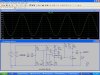
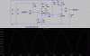
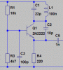
I have seen many of these little FM transmitter circuits but have never bother to sit down and analyse them in any; detail until now that it. I simply entered the audioguru's circuit into LT Spice and the sinewave was only 10mVp, I tweaked a few things and now it's 3Vp, which will deliver 60mW into a 75 hm: load. I also decided to add a diode varactor to get rid of the crappy AM output.
I'm thinking about building this little transmitter. I will obviously need to add an amplifier but I don't know what gain I require. The only thing is I don't plan to use the 1N914, I'll use the 1N4001 as the varactor.
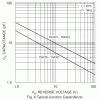
One thing I've figured out is that the tank capacitance only has to vary slightly to make the frequency deviate by 75kHz.
With a 100nH inductor assuming C is set to the appropriate capacitance:
@108MHz
+4.8fF for -75kHz
-4.801fF for +75kHz.
@88MHz
+8.872fF -75kHz
-8.875fF +75kHz
Another thing is I hear people referring to it as a Hartley or colpitts oscillator; I've done some research and it's neither of the aforementioned.
A real hartley oscillator
**broken link removed****broken link removed**
A real colpitts oscillator
**broken link removed****broken link removed**
I can't see any similarities between this FM oscillator and a either of the above.
I think it's more likely to be an oscillator based around the common base amplifier.
**broken link removed**
In my drawing the tank replaces Rc and C3 replaces Cb. C2 provides feedback from the output to the input, as the gain is Rc/Re, it's no surprise it oscillates when the collector is at the highest impedance.
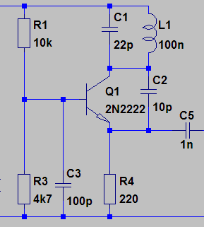
What does everyone here think?
hm: load. I also decided to add a diode varactor to get rid of the crappy AM output.I'm thinking about building this little transmitter. I will obviously need to add an amplifier but I don't know what gain I require. The only thing is I don't plan to use the 1N914, I'll use the 1N4001 as the varactor.
One thing I've figured out is that the tank capacitance only has to vary slightly to make the frequency deviate by 75kHz.
With a 100nH inductor assuming C is set to the appropriate capacitance:
@108MHz
+4.8fF for -75kHz
-4.801fF for +75kHz.
@88MHz
+8.872fF -75kHz
-8.875fF +75kHz
Another thing is I hear people referring to it as a Hartley or colpitts oscillator; I've done some research and it's neither of the aforementioned.
A real hartley oscillator
**broken link removed****broken link removed**
A real colpitts oscillator
**broken link removed****broken link removed**
I can't see any similarities between this FM oscillator and a either of the above.
I think it's more likely to be an oscillator based around the common base amplifier.
**broken link removed**
In my drawing the tank replaces Rc and C3 replaces Cb. C2 provides feedback from the output to the input, as the gain is Rc/Re, it's no surprise it oscillates when the collector is at the highest impedance.
What does everyone here think?
Attachments
Last edited: