Continue to Site

Welcome to our site!

Electro Tech is an online community (with over 170,000 members) who enjoy talking about and building electronic circuits, projects and gadgets. To participate you need to register. Registration is free. Click here to register now.

  • Welcome to our site! Electro Tech is an online community (with over 170,000 members) who enjoy talking about and building electronic circuits, projects and gadgets. To participate you need to register. Registration is free. Click here to register now.

FM transmitter, what's a matta' wit it?

Status
Not open for further replies.

zachtheterrible

Active Member
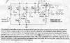
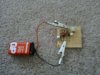
Hi, I just built this transmitter today, and wuddya know, it doesn't work. I have a couple of theories, just wonderin' if someone could give me some answers. Just to let you know, this thing isn't transmitting AT ALL, I have a little rf field detector that I built, which works great by the way, and it is showing that there is absolutely nothing coming out of there; so it isn't just transmitting on a wrong frequency. Here are my theories:
1. I have a battery aligator clipped to the circuit. Are the large clips and long leads making it not work? If they are screwing up the capacitance, would this make the circuit not work period, or just change the frequency?
2. There is a capacitor in the circuit that has long leads off of it. It is C4 in the schematic. But if that is screwing up the capacitance, wouldn't it just change the frequency? The reason I have these long leads is that I don't want to waste these components unless I know the circuit is going to work.
3. C5 in the schematic is a very old capacitor. I got it out of a garage of a house that we are moving into. It almost looks like there was an arrow pointing to one of the leads. If there is, in which direction should the capacitor be placed?
4. The antenna and inductor are just some copper wire. Should they be magnet wire or something?

Any help would be greatly appreciated.
 

Attachments

  • fmtrans.jpg
    fmtrans.jpg
    265.4 KB · Views: 858
C5 is no doubt the problem, order a good one from www.mouser.com (54 cents plus shipping), or get the assortment from Radio Shack, 272-809, which has a 5 pF cap in it. You could gambel that 272-801 has what you want, but the contents are not listed. Mouser part number: 75-10TCCV47
 
How are you constructing it? Breadboard is definitely out. You might (just might) get away with perforated board if you surround the top of the board with grounded copper foil first, and then simply use a sharp knife to remove small holes where the component leads are to be inserted through the holes (to be soldered to the bottom of the perf board). At least, you should do that for the RF section (the transistor on the right). Or use, "ugly" construction: copper clad board substrate with connections made hanging in the air, and anchored at ground points to the copper clad board. Other than that, looks like it should work if you use reliable components. It is a Colpitts type CB oscillator, I think.

Jem
 
What is perf board? I'm using pc board to put the circuit together. Here's a picture, please excuse the piece of junk digital camera. Can I substitute a different value for C5? such as 3 or 5 pf?
 

Attachments

  • 1_168.jpg
    1_168.jpg
    58.1 KB · Views: 835
zachtheterrible said:
What does C5 do? Can I use a 4 or 5 pf? I have new ones.

C5 provides the positive feedback for the oscillator, it's value isn't critical - I've often used two short pieces of insulated wire twisted together when I've thrown one together and not had a suitable capacitor.
 
L1 is there. It is that white blob in the top right of the circuit board. It's covered in hot glue, so it won't get messed up.
 
I did not recognize the oscillator circuit, so I built it to see if it did oscillate. I don't have the means to measure the frequency but with 9 volts applied, the emitter voltage is 7 volts and the base voltage is 6 volts. Since the base is negative relative to the emitter, it must be oscillating. I suggest you measure the base and emitter voltages of your circuit to see if it is similar.
 
I measured the emitter and base of the transistor and got NOTHING. Just to make sure that I am measuring right, I put the both leads of the multimeter on the base, and then the emitter. That's right, right? (wouldn't be surprised if it isn't) I also replaced C5 w/ a new capacitor it's value is 5 pf, cuz i don't have 4.7 pf.
 
I did what you said, and didn't get anything. Absolutely nothing on the base, but on the emitter, I got .7 volts. I know that there are no wiring problems, because I have checked the circuit over a number of times to make sure everything is placed correctly, and it is. Could there be anything else that commonly goes wrong with this kind of thing?
 
I can't think of any way that a correctly wired circuit could give those voltages. What is the voltage across the 10K base resistor? What is the collector voltage relative to the emitter?
 
I tested the 10k resistor, and I got nothing, not a bloody thing, I even went down into the mv. I then measured the resistance of the 10k in the circuit, with no power on the circuit and the resistance jumped, and then went to zero. Is that ok to measure the resistance of the 10k while it is in the circuit? Sorry for my thickheadedness, but when you say measure collector voltage relative 2 emitter, does that mean just put the leads on collector and emitter? I did what i think you meant, and got .75 volts. Is there any way of making sure that the transistors aren't fried while they are still in the circuit? Thanks for all your help everyone, especially russlk . . .
 
Please tell me how to measure the collector relative 2 the emitter. I think that maybe I've got a faulty part.
 
To measure the collector relative to the emitter, put the black lead to the emitter, and the red lead to the collector. I don't see any evidence that you have a defective part, non of your measurments make any sense. Try these measurments: battery negative to battery positive, battery negative to coil where it connects to collector, battery negative to emitter. Battery negative to top of 10k resistor.
 
Here goes:

Collector relative to emitter=.75v

Batt neg 2 pos=7.97v (old battery)

Batt neg 2 collector=7.97v

Batt neg 2 emitter=7.19

Batt neg 2 top of 10k=7.92

Couldn't it be that I've bad transistor(s)? That would be the part most likely to go cuz if u connect them backwards, aren't they gone?
 
:D :) :p :eek: :lol: :wink: HALLELUJAH!!!!!!! :D :) :eek: :lol: :p :wink: IT WORKED!!! I don't believe it!!

But it still doesn't work perfectly. I've got a couple of questions.
1. I can hear myself, but very crackly, is this just a bad mic?
2. What does C3 do?
3. What are some reasons C3 may have gone bad? It has never been connected to anything more than 9 volts.
4. I am getting harmonics all the way up the dial. How far up the dial do these harmonics usually go? And how do you stop them? Are they wasting energy of the battery? And what causes them?

Russlk, you have been MOST helpful :D , and I appreciate it VERY greatly.
 
1. Could be the mic or distortion in the first stage, I did not analyze it.
2. C3 is a bypass to put the base at AC ground.
3. Most likely a mechanical or temperature overstress, or just random failure.
4. Harmonics are normal, you may hear up to the the 10th or 20th harmonic. A lowpass filter is usually used to prevent them from getting to the antenna, but I don't think eliminating the harmonics will affect the power at the desired frequency.
 
Status
Not open for further replies.

Latest threads

New Articles From Microcontroller Tips

Back
Top