vne147
Member
Hello everyone. A friend of mine asked me to build him a small FM transmitter so he could broadcast an mp3 player to his car stereo. I found plans online and built the circuit on this page:
**broken link removed**
I believe I didn't make any errors in laying out the schematic or board and I'm pretty sure there are no problems with the board itself (i.e. broken traces, shorts, etc.) The only problem is, it doesn't work.
When I try to perform the steps at the bottom of the page labeled "Test & adjustment" I'm running into problems. The voltage at TP2 is 5V and adjusting the slug of L1 makes absolutely NO difference. The type of adjustable coil I'm using is this:
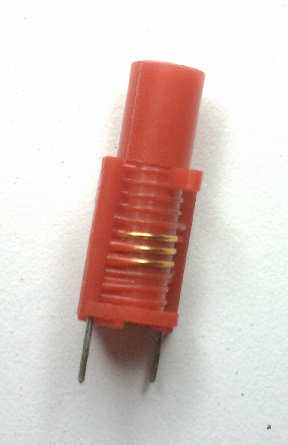
I've done some poking around trying to troubleshoot the problem and I've discovered that the voltage at the end of L1 that's not connected to ground is 0V. Also, the voltage at pin 9 is about 2.9V.
Lastly, and I'm not sure if this is normal but the BH1417F IC gets hot when the circuit it powered. It's not so hot that it burns my finger but it's noticalby warm.
Anyway, if anyone has any ideas about what might be wrong or how I can further troubleshoot please, please, please, let me know. If you need more information to help me just let me know and I'll provide whatever I can.
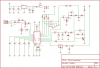
I also posted a screen shot of my .sch file. I didn't want to post the file itself because it uses a lot of modified libraries but if anyone wants it I'll zip the .sch, .brd, and all the necessary .lbr files.
As always, thanks in advance for any help you can offer me.
**broken link removed**
I believe I didn't make any errors in laying out the schematic or board and I'm pretty sure there are no problems with the board itself (i.e. broken traces, shorts, etc.) The only problem is, it doesn't work.
When I try to perform the steps at the bottom of the page labeled "Test & adjustment" I'm running into problems. The voltage at TP2 is 5V and adjusting the slug of L1 makes absolutely NO difference. The type of adjustable coil I'm using is this:
I've done some poking around trying to troubleshoot the problem and I've discovered that the voltage at the end of L1 that's not connected to ground is 0V. Also, the voltage at pin 9 is about 2.9V.
Lastly, and I'm not sure if this is normal but the BH1417F IC gets hot when the circuit it powered. It's not so hot that it burns my finger but it's noticalby warm.
Anyway, if anyone has any ideas about what might be wrong or how I can further troubleshoot please, please, please, let me know. If you need more information to help me just let me know and I'll provide whatever I can.
I also posted a screen shot of my .sch file. I didn't want to post the file itself because it uses a lot of modified libraries but if anyone wants it I'll zip the .sch, .brd, and all the necessary .lbr files.
As always, thanks in advance for any help you can offer me.
Attachments
Last edited: