Continue to Site

Welcome to our site!

Electro Tech is an online community (with over 170,000 members) who enjoy talking about and building electronic circuits, projects and gadgets. To participate you need to register. Registration is free. Click here to register now.

  • Welcome to our site! Electro Tech is an online community (with over 170,000 members) who enjoy talking about and building electronic circuits, projects and gadgets. To participate you need to register. Registration is free. Click here to register now.

FM transmitter design improvements needed.

Status
Not open for further replies.

Drewvogel2

New Member
Dear members,
I have recently picked up an interest in electrical engineering in it's most simple regards. I am an electrician by trade. I have been studying circuit components and reasonably know ohms law and the laws of series and parallel circuitry.
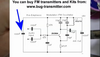
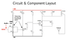
I decided upon this project which was online. I created the circuit and the circuit works, but there are issues.
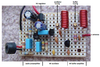
1. The frequency output is not strong/stable. Holding the antenna with two fingers helps signal transmit clear. ( The antenna is soldered to the center coil of the inductor.
I don't need perfection, but I would appreciate some simple ideas to improve the stability of the transmitter. Thanks!

Ps! I reached out to the creator and he had similar issues with his. Turned out it was his senior year project haha!
Thanks! Andy.

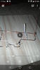
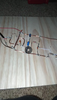
PS. Waiting on another capacitor for the inductor branch. That's the twisted pair currently soldered in. Used a trimmer capacitor at first, but just compound the instability.
 

Attachments

  • Screenshot_20201206-002600.png
    Screenshot_20201206-002600.png
    287 KB · Views: 236
  • Screenshot_20201207-192001.png
    Screenshot_20201207-192001.png
    1.5 MB · Views: 230
  • Screenshot_20201207-192018.png
    Screenshot_20201207-192018.png
    1.5 MB · Views: 211
Last edited:
Because of the overall construction and size, any movement anywhere near it will change the circuit capacitance and frequency.

If you want it to be rather more stable, I'd suggest you rebuild it "dead bug" style on a bit of copper circuit board, keeping all the sizes and spacings as small as reasonably practical.

Solder the component that connect to 0V (-9 on the drawing) directly to the copper and use them to support the non-grounded points.

This article shows that technique, plus others:

[Note that DIY transmitters are restricted or totally illegal in most places, but if you cannot even pick it up strongly yourself, it's not likely to be causing interference to others; just don't try and make it over-powerful].
 
Thank you very much for your reply! I realize that any transmitter this size or stronger could cause interference and is illegal. I have always been fascinated by radio and would be enthralled to build a transmitter that works exceptionally and I can thus study the workings of the circuit with some meters and use it up at my farm in north jersey (7 acres).

This is actually the second time I've built it, the first one was 3.5" by 2" but it was not on a copper clad or perforated board, just mounted on Some plastic I had. Results were way better this time than before though.
Thank you for the article, I will most certainly study it.
Regards! Andrew.
 
Dear members, I have a break in the case,
There's more wrong with this transmitter than I thought, I turned on my electric radio and went into Auto-Tune, and this transmitter is attempting to transmit on every blank frequency the only blank frequencies around my area are 88.3 92.5 and 104.5 and on every one of these frequencies I can detect my station only as described in my above post though. This includes being in close range to the transmitter and aiding by holding the antenna .
The inductor is supposed to determine the frequency which is broadcast by the unit based upon the number of coils and spacing, something has clearly superseded the inductors ability to dictate this, I am up for conjecture on what could be causing this . Thanks Andrew!
 
With the way it's built at present, various parts could be resonating or the oscillator could be squegging, where it biases itself off as soon as oscillation starts to build up.
 
With the way it's built at present, various parts could be resonating.
Thank you very much for the input. I will learn from everything your telling me. I'm responsible with this circuit and promise to be responsible in it's operation. I will try anchoring the circuit down to prevent oscillating components, and I will research the rest of your comment. Thank you. Ordering some perforated circuit boards to practice and a few new designs to try.
 
Thank you very much for the input. I will learn from everything your telling me. I'm responsible with this circuit and promise to be responsible in it's operation. I will try anchoring the circuit down to prevent oscillating components, and I will research the rest of your comment. Thank you. Ordering some perforated circuit boards to practice and a few new designs to try.

Layout at VHF is CRITICAL - it needs to be as small as possible, and carefully laid out.

It doesn't help that this circuit is crap, it's only a toy, and will drift all over the place for any reason whatsoever (such as moving near it).

AudioGuru has many times posted his slightly improved version on these forums, including a proven stripboard layout. However, this only makes a poor design 'better', it doesn't make it 'good'.
 
AudioGuru has many times posted his slightly improved version on these forums, including a proven stripboard layout. However, this only makes a poor design 'better', it doesn't make it 'good'.
[/QUOTE]

Dear Nigel,
Thank you very much for the input.
I understand this is a basic circuit, and was hoping for criticism so that I can improve this design.
I am very new to circuitry and am nearly learning the fundamentals of how these components interact and the flow of current through them. I will research audioguru's work and implement some of his ideas so I can create a sound transmitter circuit which is my first objective as a novice circuit engineer.
Thanks! Andrew.
P.S I have obtained some circuit engineering classroom DVDs which I am watching to help me help myself.
 
Somebody posted a simple FM transmitter circuit similar to yours and asked why it did not work. Its parts were very far apart almost as much as yours.
I made it and fixed/improved it with 4 modifications:

1) I made its oscillator compactly on a stripboard, because long wires have inductance and have capacitance between them.
2) Its radio frequency changed as the battery voltage ran down, so I added a 5V regulator.
3) its radio frequency changed if something moved towards or away from its antenna, so I added an RF buffer amplifier to isolate the oscillator from the antenna.
4) It sounded muffled so I added a preamp with correct pre-emphasis (treble boost) to match the de-emphasis (treble and hiss cut) used on all FM radios.
Its range is across the street to a cheap radio or is 2km across a large river valley to a high quality car radio or stereo. Its distance is probably illegal.

I simulated your circuit and found a very small amount of pre-emphasis. I could not fix it much by changing parts values so it needs a preamp with pre-emphasis like mine has.
 

Attachments

  • fm tx mod4.GIF
    fm tx mod4.GIF
    46.2 KB · Views: 224
  • FMtx mod4 layout.png
    FMtx mod4 layout.png
    1.4 MB · Views: 215
[QUOTE="

I simulated your circuit and found a very small amount of pre-emphasis. I could not fix it much by changing parts values so it needs a preamp with pre-emphasis like mine has.
[/QUOTE

Audioguru,

Thank you very much for looking into my circuit! I have looked at yours and am very eager to build it. I have perforated circuit boards on the way with many 2N3409 transistors and other components. The only difference I see is I'm using an audio jack instead of a mic, but I imagine hookup is the same. I appreciate your insight and hope I can learn allot about these audio circuits through all this information.
With best regards,
Andrew.
 
My circuit board is Perforated Stripboard that has parallel strips of copper that form a lot of the wiring. A few jumper wires and all the parts are soldered to the copper strips.
Without using a microphone then remove R1 and make a 1/100 attenuator with a series 100k resistor feeding a 1k resistor to ground. The junction of the two resistors connects to the input of C1.
 
[QUOTE without using a microphone then remove R1 and make a 1/100 attenuator with a series 100k resistor feeding a 1k resistor to ground. The junction of the two resistors connects to the input of C1.
[/QUOTE]

Thank you AudioGuru!
I am collecting the components needed to complete your circuit from circuitspecialist website. Some of the capacitors are proving evasive such as the 470 pf and 100 pf. However I found the 470 pf in the form of an electrolytic which should be fine. I Used different conversions such as uf and nf, but some are just hard to find! I'll try some different web sites perhaps. I ordered a bunch of trim caps so no prob there.
As far as the audio jack swap in, it seems easy enough, I'll just draw it first and I'll check with you!
Thanks,
Andy. PS. The transmitter as it stands takes quite fondly to my old arvin tube radio. It much induct it's power from the radio haha.
 
Last edited:
470pF and 100pF are common ceramic capacitors. They are 470 and 100 micro-micro-Farads.
Electrolytic capacitors are micro-farads that are 1 million times higher.
 

Attachments

  • ceramic capacitors.png
    ceramic capacitors.png
    212.8 KB · Views: 183
Friends,
I have done some practice and trial and error. I have been learning constantly through all of this such as capacitor codes and the different varieties and there uses. I have made mistakes and corrected them.
I thought I would share my progress and keep the education going. My prototypes are getting smaller and neater. And with each design the results are better. I have so far messed with two schematics; however I'm waiting on AudioGurus circuit until I can gather all the components!
Thank you everyone for your support. These are my latest attempts. The one on the turquoise board is the original circuit I produced, but to appropriate scale, and with a proper 1/4 wavelength antenna for FM. The results are much improved. The tan prototype board is a new circuit which is much more stable, but lacks a trim capacitor so adjustment of frequency is a pain!! But plan on adding one in in replace of the 33pf cap.
PS I ordered 1000 varied resistors, 1000 varied ceramic caps and 500 electrolytics, so I'll never have a hard time finding parts again lol. Really having fun with this. Can't wait to build a radio receiver!
 

Attachments

  • KIMG1357.JPG
    KIMG1357.JPG
    403.2 KB · Views: 190
  • KIMG1356.JPG
    KIMG1356.JPG
    321.6 KB · Views: 200
  • Screenshot_20201206-214205.png
    Screenshot_20201206-214205.png
    580.4 KB · Views: 199
Last edited:
The recent schematic you show has two audio inputs but it is not stereo.
It has no resistor to power an electret mic.
It has no audio preamp to make sounds loud enough.

It says "pre-emphasis" but it has the opposite, then voices and music will sound muffled on any FM radio.
The 47k series resistor feeding 1nF to ground cuts frequencies above 3.4kHz. Pre-emphasis for FM in Europe and Asia boosts frequencies above 3.3kHz.

My transmitter has its R5 and c4 boosting frequencies above 3.4kHz and since C5 is important for the oscillator then r4 is only 470 ohms so that C5 cuts frequencies that cannot be heard above 34kHz.
 
My transmitter has its R5 and c4 boosting frequencies above 3.4kHz and since C5 is important for the oscillator then r4 is only 470 ohms so that C5 cuts frequencies that cannot be heard above 34kHz.
[/QUOTE

Thank you AudioGuru!
I have collected most of the components to build your circuit, you gave me instructions on converting the mic to an audio jack via a 1/100 atentuator. An atentuator from my research decreases the power of the signal without distorting it. I just want to make sure I build it right. I would get rid of R1, as you said and then add the 1/100 atentuator feeding a 1k resistor to ground. What does an atentuator consist of? I am researching myself In the meantime,!
Thanks, Andy.
 
The attenuator is a two-resistors voltage divider. The input signal is fed to the series 100k resistor plus 1k resistor to ground then the attenuated signal across the 1k resistor is 1/101 times the input signal level. You might need to adjust the resistor values depending on how loud you talk (sing?) or how far away from the mic you are.
If you tune the transmitter to the radio frequency used by a radio station and you are causing illegal interference to a listener who complains, then you will have a visit from the RF cops.
 
Thanks, I appreciate your help, in this case it's just my mp3 player via audio jack. And these are just a hobby I enjoy. I use an empty frequency, and the signal is usually less than 50 meters, strongest within 10 meters. Plus I'm just an entry level guy learning how these circuits work.
 
My FM transmitter goes across the street to a cheap radio or 2km across a large river valley to a sensitive hifi or car radio. Many people have sensitive radios.
A magazine project and kit (Micromitter) has an RF attenuator on its antenna output for use in a car.
 
Status
Not open for further replies.

Latest threads

New Articles From Microcontroller Tips

Back
Top