Electro Tech is an online community (with over 170,000 members) who enjoy talking about and building electronic circuits, projects and gadgets. To participate you need to register. Registration is free. Click here to register now.
Welcome to our site! Electro Tech is an online community (with over 170,000 members) who enjoy talking about and building electronic circuits, projects and gadgets. To participate you need to register. Registration is free. Click here to register now.
it has various fm transmitters. You should be able to find pretty much what you are looking for.
to input from your computers sound card, you need to un-wire the mic, and connect it to the output from your computer's sound card. remember that the output from your computer will be stereo...
ermm, i'm not sure, however, I think that if (where the diag says to connect the telphone line) you connect the ground and one of the signals from your sound card, it should work
try it, see what happens.
p.s. for pages in other languages, try using google translation. its not very clear, but it is just good enough.
hi i am in the first year of universiy i just want to know how to make a fm transmiter and where can i find the circute explanatin about it for example why we should conect the transistor to the otheres
please give me a site to find it
best regadrs
my Email: befor6years@gmail.com
bye
The simple FM transmitter is too simple:
1) Its tuned circuit is connected directly to the antenna. So if anything gets near it then its frequency will change.
2) It doesn't have a voltage regulator. Then its frequency will also change as its battery voltage runs down.
3) Its input sensitivity is about 5mV. The output from your sound card is much too high and an attenuator is needed.
4) It doesn't have pre-emphasis (treble boost) like FM radio stations have so it will sound very muffled (without treble audio frequencies) when heard on an FM radio.
5) It has a very weak output power and might not have a range to across the street.
AudioGuru, you've posted this before and it's actually kept me from building the "simple fm transmitter". Do you know of a circuit that incorporates the pre-emph?
Also, how would we isolate the antenna? Is a capacitor or inductor appropriate? I know on high power tube FM tx's, the coupling is inductive (or appeared to be so to my inexperienced eyes).
Would slapping a voltage regulator IC on the power input stop frequency drift? I've read only very little about voltage regulators, so I don't know if a battery would be a fitting application.
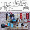
My FM transmitter has an RF amplifier transistor to isolate the antenna from the oscillator's tuned circuit.
It has pre-emphasis so it sounds crisp and clear.
It has a low dropout voltage regulator so its frequency doesn't change as the battery voltage runs down.
But it is not simple and it is not stereo.
Have you actually measured the RF power using calibrated equipment?
The simulation I performed on your transmitter gave a waveform of about 3.3V peak, which would deliver 76.2mW into a 75hm: load, given that there will be losses in the aerial the final ERP will probably be about 60mW.
Even higher RF output appears purposeless, as the impedence matching and ANT gain matter for radition efficeiency- once Audiogruru quoted the coverage with this MOd4 device as few KM-- it only proves how effective were his ANT management .
My antenna was just an 80cm piece of wire hanging out a window. The range was across a very wide and deep river valley to my very sensitive car radio. The range was much less to my Sony Walkman radio.
This site uses cookies to help personalise content, tailor your experience and to keep you logged in if you register.
By continuing to use this site, you are consenting to our use of cookies.

")