Continue to Site

Welcome to our site!

Electro Tech is an online community (with over 170,000 members) who enjoy talking about and building electronic circuits, projects and gadgets. To participate you need to register. Registration is free. Click here to register now.

  • Welcome to our site! Electro Tech is an online community (with over 170,000 members) who enjoy talking about and building electronic circuits, projects and gadgets. To participate you need to register. Registration is free. Click here to register now.

FM microphone

Status
Not open for further replies.

ImpulsE041993

New Member
hello guys, i need ur help in explananing the circuit flow of my fm mic.
this circuit is not mine, i only copy it from this site
**broken link removed**
how does the audio amplifier , tank circuit, and rf amplifier works in this circuit.
any help will be greatly appreciated.
 

Attachments

  • bug5c.jpg
    bug5c.jpg
    13.3 KB · Views: 249
Harry Lythall's transmitter circuit above has a number of faults.
1. The 4k7 feeding the electret microphone is too low. It should be 47k to prevent overloading the microphone.
2. The coil on the PC board has a very low "Q" and will produce a very low output.
3. The 12p across the coil is too low. It should be 33p to 47p and the coil should be changed to 6 turns 3mm dia enamelled wire so the two components have the correct L-C ratio.
4. There is no way to adjust the frequency of transmission.
5. The coupling capacitor to the final transistor is too high. It should be 47p maximum.
6. A BC557 transistor is not a good RF amplifier.


<mod edit: self promotion deleted>
 
Last edited by a moderator:
Harry Lythall's transmitter circuit above has a number of faults.
1. The 4k7 feeding the electret microphone is too low. It should be 47k to prevent overloading the microphone.

You are the only person in the world who powers an electret mic with a resistor value that is WAY TOO HIGH!
An electret mic draws 0.5mA and needs a few volts so it is not overloaded by loud sounds.
Then 10k ohms will be perfect. 4.7k is fine.

The preamp transistor has an input impedance of about 1.5k ohms so if you use a low current and a high resistor value to power the mic then it is severely attenuated.

2. The coil on the PC board has a very low "Q" and will produce a very low output.

Maybe, but his circuit and kits work fine.

3. The 12p across the coil is too low. It should be 33p to 47p and the coil should be changed to 6 turns 3mm dia enamelled wire so the two components have the correct L-C ratio.
3mm wire is HUGE!

4. There is no way to adjust the frequency of transmission.

I didn't look at his instructions but it would be tuned by spacing apart the turns on the coil or tightening the spacing.

5. The coupling capacitor to the final transistor is too high. It should be 47p maximum.
It doesn't matter. But it will work the same with 47pF.

6. A BC557 transistor is not a good RF amplifier.
It doesn't matter, it works fine. EVERYBODY has a common BC557 but an RF transistor is rare.
 
audioguru
I am just telling you the correct way to design a circuit.
You obviously have never built any of these circuits as you don't know what you are talking about:
"An electret mic draws 0.5mA and needs a few volts so it is not overloaded by loud sounds."
"3mm wire is HUGE!"
"tuned by spacing apart the turns on the coil"

Your faulty circuit is aready covered on my "Spot the Mistake" article. Page 9

Here is a list of the faults in YOUR circuit:

Next we have an FM transmitter that looks to be well-designed. Apart from the complex circuit, there are a number of fundamentally incorrect features that make the circuit unreliable.
And the layout is one of the worst I have seen for an FM transmitter.
This type of circuit should NEVER be laid out on strip-board and any type of board that has extra conductive lines as they create "wires" that radiate signal and they can be so effective that all the signal is radiated and none is retained to keep the oscillator in a state of oscillation. That's why this type of layout can result in non-operation.
The first item we will look at is the "Q" of the tank circuit.
This is a factor known as "Quality" and comes from the fact that an inductor will produce a voltage (of opposite polarity) that can be many times higher than the voltage applied to it.
And that's what a circuit like this FM transmitter does. The voltage produced by the capacitor and parallel inductor on the collector, will produce a voltage many times higher than the 5v on the rail.
These two components are called a TANK CIRCUIT and to get them to produce a high voltage, the energy stored (and released) by the capacitor must be equal to that of the inductor. The two work like tipping water from one jug to another of the same size and back again. If one jug is smaller, we only get the energy from the smaller jug.
In this case the 5-35p air trimmer will be set at about 20p for 90MHz while the energy stored in the 10 turn coil will be twice that needed. The 10 turn coil should be reduced to 5 turns and the capacitor should be increased to 39p - 47p. This will give the circuit a higher "Q."
With a low Q, the energy through C7 (4p7) will be very small.
We don't know how or where the tracks are cut on the "strip-board" but you can see some of the track will connect to the end of the 4p7 that goes to the emitter.
This track acts like a "transmission line" and since it is very wide, it will have a high value of radiation.
This means a certain amount of the energy delivered by the 4p7 will be lost to the surroundings and any handling of the project will cause drifting or it could come to a point where the oscillator fails when handled.
In addition, some of the energy delivered by the 4p7 is being lost via the 30p coupling capacitor and the circuit may fail to work.
The circuit may be successful as the oscillator transistor is being heavily driven via the 220R in the emitter. This may overcome the short-falls in the other design-concepts, but the 30p "take-off" should be connected to the collector of the oscillator stage as it will transfer a lot more energy.
High frequency circuits like this need to be designed so the power rails are "tight." This not only means electrical and electronic "tightness" but also physical tightness.
The 1n across the power rails for the output stage is insufficient to give good tightness (it should be 22n) and the placement of the components on the board is far too spread-out.
This makes the project very susceptible to handling and drifting.
Since the output transistor is a buffer, the 22p on the antenna is not needed and simply reduces the range. The 30 inch antenna will give a very small range.
The 10k resistor on the electret mic is too low for our high-sensitivity microphones. It should be 47k for 5v rail.
The 100u electrolytic across the battery is totally unnecessary as the current consumption is only a few milliamp. In addition, the 100u on the output of the regulator needs to be only 1u to 10u.
Overall, I consider the circuit is taking 2 - 3 times more current than it needs.
Our 9v Voyager circuit consumes 7-10mA for 800metre range. This circuit will consume more than 25mA.
One final point. The air trimmer should be in parallel with a capacitor (39p) so the trimmer is only adjusting a small amount of the total capacitance. This makes it easier to tune across the band and set the frequency.


Hi Collin,
My FM transmitter is not my design, I simply fixed one that did not work.
It works perfectly and sounds much better than yours because it has pre-emphasis like all FM radio stations have. Yours sound muffled with reduced high audio frequencies above 2.1kHz in North America like a stereo with its treble tone control turned all the way down. In Europe and down under yours sound as bad as a telephone or an AM radio.

I built it on strip-board with all the strips cut as short as possible. Two pcbs have been designed for my FM transmitter and they are the same size as my compact stripboard layout. Other people have built it and say it works fine.

I used a low-dropout regulator that MUST HAVE a 100uF output capacitor. Yours don't have a regulator so their frequency changes as the battery voltage runs down, mine doesn't.

It uses a half-wavelength antenna like most FM car radios use.
Its range is illegally very far. I gave up walking and took my car 2km away and it was still heard across a huge river valley even though a low power foreign language radio station was on the same frequency. All FM station frequencies are used in my area.
 

Attachments

  • low dropout regulator.PNG
    low dropout regulator.PNG
    16.4 KB · Views: 231
audioguru

Read the whole data sheet:

http://www.datasheetcatalog.org/datasheet/nationalsemiconductor/DS005254.PDF

Another regulator characteristic that is noteworthy is that
stability decreases with higher output currents. This sensible
fact has important connotations. In many applications, the
LM2931 is operated at only a few milliamps of output cur-
rent or less. In such a circuit, the output capacitor can be
further reduced in value. As a rough estimation, a circuit that
is required to deliver a maximum of 10 mA of output current
from the regulator would need an output capacitor of only
half the value compared to the same regulator required to
deliver the full output current of 100 mA. If the example of
the capacitor in the circuit rated at 25C junction
temperature and above were continued to include a maxi-
mum of 10 mA of output current, then the 22 uF output
capacitor could be reduced to only 10 uF.
 
Last edited:
you can set the frequency of transmission, it has a gimmick capacitor added across the 12p tuning capacitor .
Here's the image
 

Attachments

  • bug5c (2).jpg
    bug5c (2).jpg
    23.7 KB · Views: 223
The Tank circuit is an LC resonance.
The oscillator in all these simple FM transmitters is a Colpitts type.
Look at them in Google.
 

ImpulsE041993, I have already explained the fact that the Tank Circuit is covered on Talking Electronics website via the link provided. Here is the explanation:

The TANK CIRCUIT.
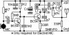
This is the coil and capacitor in the collector of the oscillator transistor.
Even though these two components are classified as "passive" - and do not amplify (as separate items), when they are connected in parallel, they form a circuit known as a TANK CIRCUIT and actually produce a waveform that is larger than the supplied voltage. These two components set the frequency of the circuit and when they are operating correctly, the output will be a maximum.

In the circuit provided, the inductor is printed on the circuit board. This type of inductor has very poor immunity to surrounding capacitance and the circuit will drift when the board is touched. In addition, this type of inductor has very poor capability of returning magnetic flux to keep the circuit oscillating and thus it will produce a very low “Q” value.

When power is applied, the oscillator starts to operate due to the 2k2 bias resistor on the base. The actual voltage on the base is created by the load from the previous transistor plus the current taken by the RF stage.
The next point to note is the base is held rigid by the 1n. This capacitor has a very low impedance at 100MHz, so it holds the base very firm.
Now we come to understanding how an NPN transistor "turns on."
It can be turned on in two ways. The emitter can be held rigid and the base can be raised to 0.6v and if the voltage is raised slightly more and the base is fed with current, the transistor will conduct and current will flow in the collector-emitter circuit.
The other way to turn on an NPN transistor is to hold the base firm and lower the emitter voltage. Once the emitter is lower than the base by 0.65v, the transistor turns on and if the emitter is lowered slightly more, the transistor turns on more.
This may be difficult to visualise, but this is occurring in the oscillator stage and is called a COMMON BASE configuration.
The transistor turns ON and current flows through the collector-emitter. This current also flows through the inductor printed on the board.
The coil does not get energy instantly because it resists any quick flow of current into it due to magnetic flux generated by the current creating a “back-voltage.” In addition, the voltage across the 12p capacitor takes time to increase.
We are only talking about milli-microseconds, but this is the “time-values” for the circuit.
As the 12p charges, the voltage on the collector decreases and this voltage is passed to the emitter via the 2p7.
We have already explained the fact that the transistor is turned on in this arrangement by decreasing the voltage on the emitter.
The transistor gets turned on more and more. The 12p charges and the inductor produces maximum flux.
Up to this point in time the magnetic flux is called EXPANDING FLUX and this expanding flux produces a voltage across it that allows the 12p to charge.
Eventually the transistor cannot be turned on any more. The 12p is charged and the inductor has maximum current flowing through it.
But this current is not increasing and the voltage produced by the inductor no-longer increases.
Some of the energy from the inductor gets lost to the surroundings in the form of electromagnetic radiation and the voltage across the 12p reduces. This voltage-reduction is transferred to the emitter via the 2p7 and the transistor starts to turn off.
The current through the inductor reduces and this causes the magnetic flux to start and collapse and produce a voltage across it OF OPPOSITE POLARITY. This has the effect of firstly discharging the capacitor and then starting to charge it in the reverse direction.
As soon as the magnetic flux starts to collapse and produce a “reverse voltage,” this voltage is passed to the emitter via the 2p7 and the transistor starts to get turned off.
Very soon the transistor is completely turned off and it can be considered to be OUT OF CIRCUIT.
We now have just a coil and capacitor with the coil delivering energy to the capacitor in the reverse direction.
Now, here is one of the amazing things of an inductor.
The collapsing magnetic flux will produce a voltage (in the opposite direction) that is higher than the original supplying-voltage.
The size of this voltage is (as a percentage) is due to the quality of the inductor and this is known as the “Q” value.
The value of “Q” can be as high as 10, 100 or even 1,000 but in this case the quality of a printed coil is very low.
Since there is no transistor in the circuit, the voltage produced by the inductor is passed to the capacitor. However a wire is connected to the capacitor (called the antenna) and since this voltage is increasing very quickly, some of the energy flows through the wire and escapes to the surroundings as magnetic radiation.
The inductor does not have a lot of energy and eventually the voltage it delivers to the capacitor starts to decrease.
This voltage is monitored by the 2p7 and the voltage on the emitter starts to rise and the transistor starts to turn on again.

It’s as simple as that.


The collector of the transistor has the tuned LC resonant parts connected to the positive supply voltage.
The transistor conducts and its collector swings almost to its emitter that energizes the inductor and charges the capacitor to almost the emitter voltage. Then the transistor is cutoff and the energized inductor discharges then charges the tuning capacitor to a positive voltage that is about double the supply voltage. Then the transistor is turned on again.
 
This is all meaningless:

The transistor conducts and its collector swings almost to its emitter that energizes the inductor and charges the capacitor to almost the emitter voltage. Then the transistor is cutoff and the energized inductor discharges then charges the tuning capacitor to a positive voltage that is about double the supply voltage. Then the transistor is turned on again.

Read my discussion.
 
Correct me if I'm wrong, the function of the 1nC capacitor connected to the base of the tank circuit transistor to the ground is to hold the base of the transistor to the ground making the transistor a common base configuration.
does that 1nC capacitor also functions as a blocking capacitor? it allows dc current to pass and blocks AC current?
 
Correct me if I'm wrong, the function of the 1nC capacitor connected to the base of the tank circuit transistor to the ground is to hold the base of the transistor to the ground making the transistor a common base configuration.
Yes.

does that 1nC capacitor also functions as a blocking capacitor? it allows dc current to pass and blocks AC current?
That is backwards. A capacitor passes AC and blocks DC.
The capacitor grounds the base for 100MHz frequencies but allows the base to have DC so it can work.
 
Last edited:
Status
Not open for further replies.

Latest threads

New Articles From Microcontroller Tips

Back
Top