DigiTan
New Member
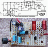
A few months ago I found this schematic for a miniature FM transmitter. I can't find the original thread anymore, but I managed to print the schematic while the topic was still fresh. I built two of these, but when I had trouble with the first, I sent second one to the oscilloscope. Here is the circuit I'm referring to...
**broken link removed**
I'm powering it off a 3V coin battery. When I read the antenna's voltage from the Q1 collector (with respect to the negative battery terminal), I see a damped sinusoid that is 104.17MHz, but only 100mV peak-to-peak. Then it dies out within a half dozen cycles, disappears for 12.8ms, and repeats.
I had to substitute a few parts that we're available to me:
1. Q1 PN3563 was replaced by an NTE108.
2. I substituted the tuning capacitor C2 with one that had a 0.5pF - 8pF range instead of 1pF - 6pF. In case I could tune the entire FM band.
3. Originally, I tried an electric mic. When it didn't work, I read from Nigel or audio that its impedance would be too high. So I now have an 8ohm miniature speaker as the "audio input."
That damped sinusoid seems accurate enough frequency-wise. I got readings ranging from 98MHz to 107MHz with just a partial turn of the tuner; so that's all good. Any idea why the amplitude is only 100mV or why this damped sine only happens every 12.8ms? I have some screenshots from the scope if it will help...
Last edited: