Electro Tech is an online community (with over 170,000 members) who enjoy talking about and building electronic circuits, projects and gadgets. To participate you need to register. Registration is free. Click here to register now.
Welcome to our site! Electro Tech is an online community (with over 170,000 members) who enjoy talking about and building electronic circuits, projects and gadgets. To participate you need to register. Registration is free. Click here to register now.
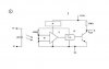
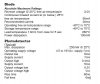
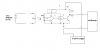
Another question, Picture 1 is the schematics for a flow sensor(from manufacturer), Pic 2 is the info for the circuits, Pic 3 is what i intend to do...Please comment and do advise....thanks
A - Voltage Regulator
B - Photodiode
C - Amplifier
D - Schmitt Trigger
All these is already inside the flow sensor when i bought them
So is it okay if i pu 100ohm resistor? And how can i know whether the LED have been burnt?
follow ohms law and don't exceed the maximum current sink specifications of the opto-coupler. Find the maximum current it can accept and use this equation for the lowest value resistor required: (resistor in ohms) = 3 / (maximum current in amps).
And how can i know whether the LED have been burnt?
Rubberlele, your link doesn't work. How about a part number?
Mstecha, you forgot to account for the LED voltage drop.
R=(3V-Vled)/Iled
For example, if you want to run the LED at 20ma, and the forward voltage of the LED is 2V@20ma, then R=(3-2)/0.02=50 ohms. You have to look at the datasheet to find out what the LED forward voltage is.
Unfortunately, the datasheet does not list the LED's I-V characteristics. They just recommend 30ma. It would be better if you could use a higher battery voltage. With a 3V battery, getting 30ma will require some experimenting using a multimeter. Also, the current will drop precipitously as the battery discharges.
I suspect you were taken in by the "Reverse voltage at 25º C free air temperature=3.0V" specification. To determine LED current, you need to know forward voltage. This spec is just a breakdown voltage, which could occur if you connected your battery backwards.
EDIT:
I found an infrared LED datasheet that shows forward voltage~1.25V@30ma. Some of the guys here probably already knew that. :roll:
so it'll be like nearly 60ohm yeah? Thanks mate! now im testing whether the LED is still okay or not, mstechca said to check the output of the opto coupler, that is the output of E, this means that i need to connect all the devices(minus the oscilloscope) and run water through it right Ron?
This site uses cookies to help personalise content, tailor your experience and to keep you logged in if you register.
By continuing to use this site, you are consenting to our use of cookies.

")