Continue to Site

Welcome to our site!

Electro Tech is an online community (with over 170,000 members) who enjoy talking about and building electronic circuits, projects and gadgets. To participate you need to register. Registration is free. Click here to register now.

  • Welcome to our site! Electro Tech is an online community (with over 170,000 members) who enjoy talking about and building electronic circuits, projects and gadgets. To participate you need to register. Registration is free. Click here to register now.

Flip-Flop

Status
Not open for further replies.
Here is something from Wiki.

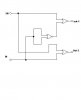
In digital circuits, a flip-flop is a term referring to an electronic circuit (a bistable multivibrator) that has two stable states and thereby is capable of serving as one bit of memory. Today, the term flip-flop has come to mostly denote non-transparent (clocked or edge-triggered) devices, while the simpler transparent ones are often referred to as latches; however, as this distinction is quite new, the two words are sometimes used interchangeably (see history).

**broken link removed**)
 
Last edited by a moderator:
Just because a flip flop is self clocked doesn't mean it doesn't have a clock meatpie.
 
No, you are messing up the word 'correct' with 'BS'.

There are a bunch of different types of FF, including RS, D, T, JK.

And there are a bunch of different types of Latches, including RS, D, T, JK.

A latch changes its state without a trigger (read clock), in other words, It is an asynchronous device. That's why async. states machines are made with latches. You can imagine a latch being a flip-flop with an infinite clock.

A f/f only changes its state with a trigger (rising/falling edge, -> read clock). it is a synchronous device. That's why sync. states machines are made with f/f's.

And that's why we have that famous Digital Systems maxim: "Every latch is a f/f, but not every f/f is a latch."
 
Just because a flip flop is self clocked doesn't mean it doesn't have a clock meatpie.

You agree then, it doesn't have an external clock ?

Push button, flip flop, No clock, as in my first statement.

Also, You will see the switch in this circuit is not connected to the clock.
 
With those circuits you are playing with RESET and PRESET inputs, they override the output and the clock, acting like a R-S latch.
 
With those circuits you are playing with SET and PRESET inputs, they override the output and the clock, acting like a R-S latch

Have another look at the circuit. It's not latching.
 
Equal logic function using only single IC NOR gate

why do we go for PIC instead of using a single logic IC??? see the attached file that is an equalent logic for the post by Vne147, but only use NOR gates. you will have a single IC two inputs two outputs and power supply.

Edit: use 4001, Quad 2-input NOR gate
 

Attachments

  • equal logic.JPG
    equal logic.JPG
    9.6 KB · Views: 178
Last edited:
why do we go for PIC instead of using a single logic IC???

I don't think he should absolutely go with a PIC. I never said it was necessary or even what he should do. I simply asked the OP if he didn't want to use one for some reason becasue a PIC would satisfy his desire to use something with a smaller package. I however still don't think there is anything wrong with using one even if there are other more straightforward solutions available. If board space was very limited, I would certainly consider it.

see the attached file that is an equalent logic for the post by Vne147, but only use NOR gates. you will have a single IC two inputs two outputs and power supply.

That's a good solution and a I'll have to admit a better idea than my NOR, AND, and inverter idea but it still uses a 14 pin IC.
 
Construct with the Basic Gates.....!

One chip containes AND gate, OR gate, NOT gate you can make use of that......!
 
With those circuits you are playing with SET and PRESET inputs, they override the output and the clock, acting like a R-S latch

Have another look at the circuit. It's not latching.

It is latching. Your inputs are PR and S, when you play with them, you latch the F/F.
 
With those circuits you are playing with SET and PRESET inputs, they override the output and the clock, acting like a R-S latch

Have another look at the circuit. It's not latching.

Again, you are latching them, every time you play with asynchronous SET, RESET, PRESET, you override the F/F with a latch. (usually SR).

The both ICs are D Flip Flops.

Pin 6 from 4013 is the PRESET input. (You latch.) -> The F/F starts cleared, due the RESET pin being pulled up, then when you press the button, the PRESET sets the output, after you release the button, the RESET pin clears the output again.
(Typical SR latch working, you are just using SR latch inside it).

Pin 4 friom 7474 is the PRESET input (You latch.) -> The F/F starts cleared, due the RESET pin being pulled down, then when you press the button, the PRESET sets the output, after you release the button, the RESET pin clears the output again.
(Typical #S#R latch working, you are just using the #S#R latch inside it).

You can see that you need to ground the CLOCK and D inputs, so that any voltage pertubations at them could change the output.
 
Construct with the Basic Gates.....!

One chip containes AND gate, OR gate, NOT gate you can make use of that......!

hi,
If the OP uses a CD4555 it is self contained, does not need 'constructing'

I think the suggestion made by 'vne' regarding a PIC is a valid point, but I dont agree with another posters method of working out the low cost.

Regarding the 'arm wrestling' about the clock, I think we all agree that some form 'external' stimulus is required to trigger the F/F, what ever type, in order to change its output state.?
 
We have two very clever answers to the problem. A CD4555 or a CD4001. That's the difference between a group of electronics professionals and a group of lawyers. The lawyers will still be working out the $5,000 fee for deciding who will think about providing an answer.
 
Last edited:
Thank you to Eric. Finally we have a TRUE statement.

Regarding the 'arm wrestling' about the clock, I think we all agree that some form 'external' stimulus is required to trigger the F/F, what ever type, in order to change its output state.?

It can be a clock or other input type. Not, "A flipflop needs a clock".


"Why do people claim to be 'designers' of their circuits, when the circuit was first published by the original ic manufacturers years ago, when all they have done is redraw it..."

Yeah I agree, and it's just the first circuit I could find to try to prove my point. I worked 11years in electronics engineering of a major auto original parts manufacturer. Not to give too much away (copyright), the auto-down function for driver's power window for one maker, used flip/flops. They where configured as a latch having both logic and push button input. The circuit used a clever idea(not mine) of sensing and amplifying the motor brush noise to switch off the motor when a stall condition occures. It didn't use a clock. A logic latch was not suitable.


To Alphacat, logic gates is the easiest solution. If you're worried about space then the SMD suggested by Eric is perfect.

Loopy
 
Last edited:
Status
Not open for further replies.

New Articles From Microcontroller Tips

Back
Top