Continue to Site

Welcome to our site!

Electro Tech is an online community (with over 170,000 members) who enjoy talking about and building electronic circuits, projects and gadgets. To participate you need to register. Registration is free. Click here to register now.

  • Welcome to our site! Electro Tech is an online community (with over 170,000 members) who enjoy talking about and building electronic circuits, projects and gadgets. To participate you need to register. Registration is free. Click here to register now.

Flashing LED circuit with photoresistor switch help needed

Status
Not open for further replies.

angie1199

New Member
Hi

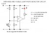
Tis me again. I've got two schematics of two seperate circuits, one that turns an LED on using a photoresistor and LM339, the other is to flash two LEDs alternately.

Both work individually although not knowing too much I have no idea how or why.

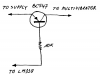
The thing is I want to turn on the flashing LEDs using the photoresistor when 'darkness falls'. I've had a go at a schematic using a transistor to switch the second circuit on, guessing how the two circuits would fit together.

Can someone take a peek at the schematic and give me the ppropriate nudge in the right direction please.
 

Attachments

  • AFLwPTS.jpg
    AFLwPTS.jpg
    34.2 KB · Views: 873
Look at the datasheet of an LM339 quad comparator IC. Its outputs are the collector of an NPN transistor. An NPN collector can sink current to ground but cannot source a positive current that is needed by the base of Q2 for it to turn on. Add a 10k resistor from the base of Q2 to the positive supply to turn on Q2 when the output of the comparator goes high.

You have the inputs of the comparator connected so that light on the phototransistor will cause the alternating LEDs to light up. Reverse the connections for the alternating LEDs to light up when it is dark.
 

Attachments

  • AFLwPTS.PNG
    AFLwPTS.PNG
    40.8 KB · Views: 487
NPN transistor.

Hi Angie1199,

You could keep the circuit as it is and replace the NPN transistor with a PNP transistor and a resistor, and remove D1. Otherwise you gonna have a
voltage drop of at least 2 volt over the NPN transistor and the diode.
 

Attachments

  • PNP.PNG
    PNP.PNG
    8 KB · Views: 440
on1aag

Thanks for that. Is there any website you can point me to that explains in plain simple english the difference between PNP and NPN transistors? I've looked and the quote I remember fully is

'The direction of the current flow differs between the PNP and NPN type. When the power supply is the side of the positive (plus), the NPN type is easy to use.'

which is why I used the NPN.

Also this is based on 12VDC. Would this work on 5VDC if I used the PNP transistor instead and removed D1?
 
audioguru said:
An NPN collector can sink current to ground but cannot source a positive current that is needed by the base of Q2 for it to turn on. Add a 10k resistor from the base of Q2 to the positive supply to turn on Q2 when the output of the comparator goes high.

So this is the difference between NPN and PNP? An NPN needs a positive 'in' to negative 'out' and a PNP needs a negative 'in' to positive 'out'?

audioguru said:
You have the inputs of the comparator connected so that light on the phototransistor will cause the alternating LEDs to light up. Reverse the connections for the alternating LEDs to light up when it is dark.
But I have the first part of the circuit as a seperate entity and instead of the transistor to the second circuit I have an LED with negative leg to the 339 and that lights up when it goes dark. While I don't question what you're saying I just don't understand why.

Ah, That's because the program I used to do the schematic had the comparator that way up and I didn't engage the brain when I inserted it and joined it up.

However, that little gem has helped me gain more knowledge in this, the mere fact that it can work in reverse :)
 
Last edited:
What values do I look at when deciding the transistors for this circuit? I've looked at a datasheet for an NPN power transistor (2N3055 15A Ic 4Vce) but there's so many values.

I assume 15A is the maximum current it can pass but what is the 4Vce? Is this the voltage required to switch it on?

[Edit] Ok, Vce - voltage across collector-emitter. And I've found out what the others mean.

So:
Vceo > 5VDC
Vcbo > 5VDC
Vebo > 5VDC
Ic > 1A
Ib > 1A
PD - 25W
Vbe(on) 1.3VDC

Would this be good?
 
Last edited:
angie1199 said:
And now it's the right way?
No. You swapped the inputs of the comparator but you also swapped the NPN transistor that didn't invert to this PNP transistor that inverts because its load is at its collector. So the LEDs light up when it is light.

You need to learn about Ohm's Law and about transistors for you to select parts for circuits.
The currents in this circuit are only a few milliamps. You wouldn't use 15A power transistors in it, you would use small, general purpose transistors.
 
audioguru said:
No. You swapped the inputs of the comparator but you also swapped the NPN transistor that didn't invert to this PNP transistor that inverts because its load is at its collector.

So change one or the other and not both?

audioguru said:
You need to learn about Ohm's Law and about transistors for you to select parts for circuits.
While I understand that, I can't find any documentation that is not 'basic' or 'advanced'. I need the bit in the middle.

I know what a base, collector and emitter are and do, but that's about as far as it goes. Also there's the added problem that there are other components in the circuit. For example the LM339. Where the transistor is connected to the 339 is of confusion to me. After all I don't want to blow the thing up.

And the two transistors at the right for flashing the LEDs. I know LEDs are small current but the circuit I used said to use a 2N3055 which is 15A. Is the author of the circuit simply being 'over cautious'?

BTW, you're a star helping like this. Glad I'm not doing my homework :)
 
angie1199 said:
While I understand that, I can't find any documentation that is not 'basic' or 'advanced'. I need the bit in the middle.

You need to start at the bottom and work up!, you can't expect to get 3 years college education from a few sites on the internet? - I don't mean to be rude?, but you're still nowhere near up to 'basic'.

And the two transistors at the right for flashing the LEDs. I know LEDs are small current but the circuit I used said to use a 2N3055 which is 15A. Is the author of the circuit simply being 'over cautious'?

No, if it used 2N3055's it was for a specific purpose, and it WASN'T flashing a couple of LED's - what's the URL you got it from?.

BTW, that part of the circuit is an 'astable multivibrator', a very basic circuit
 
Nigel Goodwin said:
No, if it used 2N3055's it was for a specific purpose, and it WASN'T flashing a couple of LED's - what's the URL you got it from?.

BTW, that part of the circuit is an 'astable multivibrator', a very basic circuit

The LED flasher is Circuit008_001.gif

The Astable Multivibrator is Circuit001_002.jpg

And this is 3rd year college???
 

Attachments

  • Circuit008_001.gif
    Circuit008_001.gif
    20.8 KB · Views: 1,018
  • Circuit001_002.jpg
    Circuit001_002.jpg
    24.4 KB · Views: 383
The huge 2N3055 transistors are used to flash powerful car lights, not LEDs, or ring a powerful bell.
This very simple circuit isn't for 3rd year colege, it is designed by sombody who never went to school.
 
audioguru said:
This very simple circuit isn't for 3rd year colege, it is designed by sombody who never went to school.

That's a bit cruel?, perhaps they went ONE day, but the school was closed? :D

It's certainly NOT anywhere near a good design (if it can be called a 'design' at all?).
 
If you are using the light detector to switch the flasher circuit, surely a MOSFET would be the best choice? Use a general purpose 2N7000 device, with an RDS-ON of 5 ohms, the voltage drop would be negligable. I think that's best, or does it need to be a P-channel? Similar P-channel devices are avialabe anyhow at a slightly higher cost. If you still want to use a BJT, which should perform fine providing the supply is high enough, use the 3906 for PNP, or 3904 for NPN, cheap and reliable :)
 
audioguru said:
The huge 2N3055 transistors are used to flash powerful car lights, not LEDs, or ring a powerful bell.
This very simple circuit isn't for 3rd year colege, it is designed by sombody who never went to school.
Well I didn't do it. I'm trying to learn here. Obviously that's not the right way to switch alternating flashing LEDs on using a photoresistor.

I think I'll experiment. If I blow up a few pennies of components, as a teacher once told me (about 28 years ago), one learns from ones mistakes.
 
Dr.EM said:
If you are using the light detector to switch the flasher circuit, surely a MOSFET would be the best choice? Use a general purpose 2N7000 device, with an RDS-ON of 5 ohms, the voltage drop would be negligable. I think that's best, or does it need to be a P-channel? Similar P-channel devices are avialabe anyhow at a slightly higher cost. If you still want to use a BJT, which should perform fine providing the supply is high enough, use the 3906 for PNP, or 3904 for NPN, cheap and reliable :)

Thanks Dr.Em, I think I'll try joining my light sensitive switch circuit to my 555 timer circuit with a transistor and see what burns, glows, or blows. I'll use big resistors first and lower them gradually.

I've recently read that when deciding on components first decide what you want it to do, then decide what specifications are important.

Obviously with a transistor voltage, current and power handling are important. So I think I'll play a bit.
 
Status
Not open for further replies.

Latest threads

New Articles From Microcontroller Tips

Back
Top