Electro Tech is an online community (with over 170,000 members) who enjoy talking about and building electronic circuits, projects and gadgets. To participate you need to register. Registration is free. Click here to register now.
Welcome to our site! Electro Tech is an online community (with over 170,000 members) who enjoy talking about and building electronic circuits, projects and gadgets. To participate you need to register. Registration is free. Click here to register now.
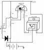
Here is a circuit. It will flash the load 3 times then stay on until the power is removed. You can calculate the R and C values from the 555 data sheet. Use a MOSFET rated for the current of the load. If the load is inductive, use a snubber diode. filter the 12 volts if this is an automotive application. Oops, Should have made the 555 timer duty cycle closer to 50 %! See the 555 data sheet.
it's a 5W/12V lamp. Correct in the assumption about automotive. Where I live "legally" you are suppose to flash your brake light on a motorcycle before you actually stop. I want to do it automatic. any other thought or help on this project would be appreciated because I only have a little of the basics down good.
what is the delay on the flashing? Do you know a good place to find the parts (when I looked on radioshack.com it didn't find the fqp3n80 and cd40175b) or are there other part numbers for them? Also, do I need to connect all the grounds and that be my output to the light? I'm not sure where wire 11 actually connects to. Are all the logic gates the same part number ( I noticed that 2 of them had 3 connections and the other 2 had 4). Does the VDD connect to pin 16 on the flip flop? Where is pin 8? The 1st symbol that you used I'm not familiar with is it a coil? Thank you for being patient with a newbie and helping me with this.
The flash rate is one second (3 flashes in 3 seconds). You can make it faster by making the 470K resistors smaller. Order parts from Mouser (www.mouser.com) I put Mouser part numbers on the schematic. Mouser does not have a minimum order. Radio Shack does not carry useful parts anymore! Yes, the grounds are common, and it occurred to me that the tail light is grounded to the frame, so it would be dificult to operate in my original design, so I have modified the schematic again. Pin 11 is not used, leave it open. Yes, VDD is +12 volts on pin 16 and ground is connected to pin 8. It is common practice to leave the power pins off the symbol, because you can find them on the data sheet. Data sheets are available at Mouser.com. Yes, the curly symbol is a coil.
I'll give you a clue! - the power supply is only 12V, so as long as it's more than that it will be fine. However, a 1uF is likely to be either 63V or 100V, and still be small.
This site uses cookies to help personalise content, tailor your experience and to keep you logged in if you register.
By continuing to use this site, you are consenting to our use of cookies.