Paul Saulnier
New Member
A while ago, my family used to have a toy dog that jumped around and barked, etc. when you clapped. When the gears messed up, my father took it apart, and took the circuitry up and gave it to me when I was young to play with. When I would clap, it would activate a motor, and stop it again when I clapped once more.
Unfortunately, all the components became separated at one point and now I have them all, but they're not connected, and I don't know how to connected.
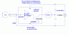
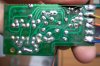
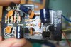
There is a motor, a battery source (1 C size battery), a microphone, and a circuit board.
The circuit has four unique points for connections to the other components. With 6 wires (two from each component) to be connected, I realize that some of them must be combined.
Can you guys give me an indication to how this should be reconnected? Which devices would likely be connected together (ie. battery connects motor which connects to circuit board which connects back to battery), etc. As well, which component would be likely to be connected to a capacitor, resistor, etc. as soon as enters the circuit board, etc.
I hope my description is help and good enough to understand. I tried searching for the numbers on the board on the internet, but found nothing.
Your help is appreciated!
Unfortunately, all the components became separated at one point and now I have them all, but they're not connected, and I don't know how to connected.
There is a motor, a battery source (1 C size battery), a microphone, and a circuit board.
The circuit has four unique points for connections to the other components. With 6 wires (two from each component) to be connected, I realize that some of them must be combined.
Can you guys give me an indication to how this should be reconnected? Which devices would likely be connected together (ie. battery connects motor which connects to circuit board which connects back to battery), etc. As well, which component would be likely to be connected to a capacitor, resistor, etc. as soon as enters the circuit board, etc.
I hope my description is help and good enough to understand. I tried searching for the numbers on the board on the internet, but found nothing.
Your help is appreciated!