Continue to Site

Welcome to our site!

Electro Tech is an online community (with over 170,000 members) who enjoy talking about and building electronic circuits, projects and gadgets. To participate you need to register. Registration is free. Click here to register now.

  • Welcome to our site! Electro Tech is an online community (with over 170,000 members) who enjoy talking about and building electronic circuits, projects and gadgets. To participate you need to register. Registration is free. Click here to register now.

First Robot

Status
Not open for further replies.

zanes

New Member
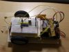
Hi guys, as some of you may know I've been working away on my first robot (a photovore). She's nearly finished (for the first version ;)) and I'd thought I'd show some pictures. Yes it's a mess, low tech and not very flashy, but it's been put together in 2 weeks, with scrounged lab time. Dah-dah! Oh, and the h-bridge and sensor boards aren't fixed in place yet (!)
 

Attachments

  • 1024x768-SNB20746.JPG
    1024x768-SNB20746.JPG
    504.4 KB · Views: 319
Nice! What's the IC? Also, is it sitting on some fabric or something? Also, what's the third wheel, if there is one? Also, can you explain what's going on at the right-hand side part of the photo (where the perf board is)?

edit: Oh, is that last one the unsecured h-bridge etc you mentioned?
 
Last edited:
Another tip for powering a robot such as your's, I would have 2 seprate (as you have) power supplies: one for Circuitry, etc and the other for motor supply. Replace your motor supply with a AA pack (AAA even) as 9V cannot hold more than 500ma usually. AAA can hold about 600-900ma, and AA can hold around 2500ma (nominal for NIMH batteries).

Try and use NIMH batteries too.
 
Very cool looking bot, Zanes!
Can't wait to see some video clips...

Krumlink, it seems Zanes was indeed using two power supplies-- the 9V battery and underneath the two battery packs. (I think that makes it three :p)
Hank-- I think the fabric stuff you're talking about looks sort of like Balsa wood?

-Omar
 
Yes I spy 2 9v's going into the H bridge. Creative solution, never seen anything like that :)
 
Oh I see now they are AA with duracell, when I saw duracell on it I for some reason automatically classified it as a 9V battery. He has a good setup. Problem with independent battery packs like that is that each pack could have completely different voltages, aka 2.4V and 3.2V. Having the same pack will drain faster but will have the same voltage. Nice robot too!
 
The board on top of the batteries to the right is indeed the h-bridges, they've been built on stripboard. The two batteries below that board are indeed 2x AA, one feeding each h-bridge. The 9v battery runs through a 7805 and runs the PIC and sensors. The IC is a PIC16F54, old, but very adequate for the task :)
As Omar said, the chassis is made of balsa wood, because I can buy and cut it myself on campus. The next version will use improved material.
The only thing stopping it working is a cable to connect the sensor boarrd to power, I forgot to rig on up whilst I was in the lab yesterday, and I can't get back in until monday :(
 
Try running both sides of the H bridge with the same pack and see how much better that works.
 
Right, got it all wired up today and we haz problems. Basically, if I wire up the h-bridge to the PIC, and program the chip to turn it on, the motor runs. If I program the PIC to turn on the h bridge port when a sensor is illuminated, and attach an LED to that port the LED lights when and as it should. When I wire up the h-bridge to that port, using the same program, nothing happens. Any ideas?
 
--------------------------------------------------------------------------------

zanes said:
Right, got it all wired up today and we haz problems. Basically, if I wire up the h-bridge to the PIC, and program the chip to turn it on, the motor runs. If I program the PIC to turn on the h bridge port when a sensor is illuminated, and attach an LED to that port the LED lights when and as it should. When I wire up the h-bridge to that port, using the same program, nothing happens. Any ideas?
What happens when you wire up the LED and the h-bridge at the same time? Alternatively, what does your voltmeter indicate is coming from the mcu pin when the h-bridge is connected?
 
Last edited:
Hmm, it looks like a voltage/current problem, as when I spin the motor shaft with my finger it runs for a while, then cuts out. I'll have a play with a pre-amp stage.
 
OK, I think I've solved it!! Basically, the output of the microcontroller is not outputting a high enough voltage when other ports are turned on (ie the other h-bridge) so I need to boost the voltage between the microcontroller and the h-bridge (the BD337 was only increasing the current). Would a buffer connected to (for example) 9 volts Vdd do this, or would it only give me unity gain. I also suspect that using 3 volts for the hbridge power circuit is cutting it very close, so the h bridge transistors need to be fully open, (Yes, a custom Nicad/NimH pack would be good. But money gets in the way)
Running the BD337 with 9V C to E, and running the h-bridge power at 9v solved the problem. I'm going to test the h bridge at some point, see what my losses are. It means another board, but it's what it needs. I'll use a 9v Nicad/Nimh pack to power the entire h bridge (including BD337s. and the current regulated 5v to power the microcontroller. What a learning curve. Loving it though :) ;)
 
Last edited:
Status
Not open for further replies.

Latest threads

Back
Top