Continue to Site

Welcome to our site!

Electro Tech is an online community (with over 170,000 members) who enjoy talking about and building electronic circuits, projects and gadgets. To participate you need to register. Registration is free. Click here to register now.

  • Welcome to our site! Electro Tech is an online community (with over 170,000 members) who enjoy talking about and building electronic circuits, projects and gadgets. To participate you need to register. Registration is free. Click here to register now.

Fire system power supply

Status
Not open for further replies.

2PAC Mafia

Member
Hi,

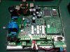
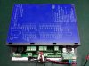
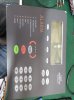
I´m trying to repair an Eltek fire alarm unit controller. There is no communication between the display unit and the other unit where all sensors are connected.
I have not experience on this unit but checking the power supply where I should get 24V I´m getting 30V so I´m thinking about the possibility of having problems at power supply and due to that the system is blocked, detecting to high voltage value (it is only an idea).
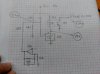
The main IC from the SMPS is an UCC3804. I have checked the feedback pin is ground connected and at Comp pin I have 1,24V. I tell you this because I thought about the possibility of having some problem at feedback circuit getting the maximum output voltage at SMPS. The Comp pin is connected to the transistor part from a HCPL354 opto at collector and emitter directly to ground. In theory, that should control the stability output at power supply.

I replaced the opto swapping with another on the board. Same behavieur. Measuring at pin 6 I have 45,8KHz PWM pulse.

Any idea why do I have this high voltage output? I think that is not normal. As always not schematics available.

Can I play with Comp pin (with a resistor) just trying to change the output?

I attach some manual I found in Internet just to show you what I´m speaking about.
 

Attachments

  • Delta_DA_Quad_Installation-guide.pdf
    419.5 KB · Views: 1,963
  • Delta_OP_Users_guide.pdf
    812.2 KB · Views: 4,076
Often a voltage divider is used to step down the output voltage for comparison with a reference and hence control the output. Perhaps a trimmer, or one of the fixed resistors making up that divider, has drifted from its intended value?
 
If you are measuring the voltage at the end of the 24 volt cable (The end connected to the load.) check if there are sense wires as well as the current carrying wires. If there are sense wires then check they are not broken. I have seen this type of fault on a 12 volt to 5 volt converter for a sat nav. As the sense wire was broken the regulator thought the 5 volts was too low. This resulted in the sat nav being destroyed due to excessive voltage.

Les.
 
According to the user manual, the supply spec states:
21 to 30 VDC
50-60mA, (normal mode)
300mA, (alarm mode)
Two monitored power supply inputs (CN1-3,4 and 5,6) to be supplied via two different circuits, so that shortcircuiting one of them will not affect the other.
So maybe your reading is normal. Could you supply your own 24Vdc as a test?
 
I dont see any symptoms of a bad SMPS yet, but if you want to adjust the output, you would see 5V =Vref on pin 8 and Vref/2=2.5V on the FB pin 2 when in regulation. By pullup FB up a bit with a resistor of suitable size, that pushes down pin 1 the comparator output more on average and that delays the Reset internally so that a higher output voltage is achieved.


more likely the communication problem is on pins 2&3 of the serial ports ( or control signals like RTS/CTS, DTR/DSR or whatever means is used. Start by checking any voltage for bipolar RS232 levels. then activity. then baud rate and check settings if any.

The correct cable either straight or crossover (null-modem) is needed to slave.

If you have a PC with a serial port, then you can monitor both directions with a breakout box on the interfaces and have 2 Rx, 1 to slave and 1 to PC. RS232 responds to 1.2V logic thresholds with bipolar levels..
 
Last edited:
I agree with Tony.
 
Thanks,

Often a voltage divider is used to step down the output voltage for comparison with a reference and hence control the output. Perhaps a trimmer, or one of the fixed resistors making up that divider, has drifted from its intended value?

No voltage divider. I made the schematic from feedback circuit so output is directly going to a 431 shunt regulator.

If you are measuring the voltage at the end of the 24 volt cable (The end connected to the load.) check if there are sense wires as well as the current carrying wires. If there are sense wires then check they are not broken. I have seen this type of fault on a 12 volt to 5 volt converter for a sat nav. As the sense wire was broken the regulator thought the 5 volts was too low. This resulted in the sat nav being destroyed due to excessive voltage.

Les.

I only see a sensing cable directly connected at the mosfet to get the temp.

According to the user manual, the supply spec states:
21 to 30 VDC
50-60mA, (normal mode)
300mA, (alarm mode)
Two monitored power supply inputs (CN1-3,4 and 5,6) to be supplied via two different circuits, so that shortcircuiting one of them will not affect the other.
So maybe your reading is normal. Could you supply your own 24Vdc as a test?

I was thinking about that but after the main output there are some other regulators as LTC1624 which is not switching, I guess because it detects too much voltage difference. As you can see in the schematics I took some measurement and the voltage at shunt regulator is 24V. I would say it´s prepared to supply 24V.

I still have to connect my power supply to see what happens, there is an optocoupler feedback from primary side going to the microprocessor too, so may be I have to supply some signal there.

I dont see any symptoms of a bad SMPS yet, but if you want to adjust the output, you would see 5V =Vref on pin 8 and Vref/2=2.5V on the FB pin 2 when in regulation. By pullup FB up a bit with a resistor of suitable size, that pushes down pin 1 the comparator output more on average and that delays the Reset internally so that a higher output voltage is achieved.


more likely the communication problem is on pins 2&3 of the serial ports ( or control signals like RTS/CTS, DTR/DSR or whatever means is used. Start by checking any voltage for bipolar RS232 levels. then activity. then baud rate and check settings if any.

The correct cable either straight or crossover (null-modem) is needed to slave.

If you have a PC with a serial port, then you can monitor both directions with a breakout box on the interfaces and have 2 Rx, 1 to slave and 1 to PC. RS232 responds to 1.2V logic thresholds with bipolar levels..

Pin 2 is directly connected to ground. Pin 8 is 5V. If I measure at diode from optocoupler I see 1,052V this means the 431 is conducting, but if I measure at the transistor from opto I measure 1,24V which I guess it should be less to regulate the PWM.
As I said I swapp already the optos with same behavieur and I replaced the 431 with not successful.

I have tested the resistors and I don´t see anything wrong.

What about pulling down a little bit the pin 1 voltage to modify the power supply output?
 

Attachments

  • Esquema feedback.jpg
    Esquema feedback.jpg
    107 KB · Views: 164
  • 1 IMG_20151007_165121.jpg
    1 IMG_20151007_165121.jpg
    126.2 KB · Views: 155
  • 1 IMG_20151007_165007.jpg
    1 IMG_20151007_165007.jpg
    92.8 KB · Views: 161
  • 1 IMG_20151016_130417.jpg
    1 IMG_20151016_130417.jpg
    86.1 KB · Views: 149
I presume the Comm ports are RS232 which normally uses a charge pump to make -5 to -10V symmetrical with V+ then sends data +V, -V . THe ports are standard for pin 2 &3 for data. If it is RS-485 then it is differential data in each direction. Can you determine which?
 
Did you determine if the DB-9 is RS232 or RS-485 (option) yet? THis is a standard serial port connector.

Normally there is a DTR or RTS signal = V+ to enable the port at each end.

RS-232 will likely have a V- created with a charge pump IC. It is common to use +/-5V bipolar data. ( which still uses TTL thresholds of 1.2V)

Measure all pins to determine V and if it can be pulled high with 1K to 5V.

E.g.
Pin V Z
1 0V open
2 0V low
3

Where is the slave unit and Serial cable? Do with both ends open and connected, enabled.
We have no idea how slaves are connected? daisy-chain? or parallel?
 
Last edited:
Did I hear it right, you said the feedback pin on the controller chip is grounded, I found that on a psu recently.
On researching it I found that some manufacts do this on opto coupled supplies, the reason its done is to speed up the response of the controller, you apply feedback to the compensation pin instead, which basically bypasses the error op amp in the controller removing its delay.
So look for the feedback going to the comp pin, assuming other ideas mentioned didnt work.
 
Hi Tony,

Sorry, I had to put the job apart as I had other repair jobs to do, I have too much work...

About this unit I was focused on power issues before checking communication things. As I told you there are more dc-dc on board, for example a LTC1624 which was not working...
About communication I guess it uses e-bus which I didn't check exactly what it is, it could be RS485 as it uses 2 wires.

Thanks Dr Pepper, I'm agree with you. I have in mind to change como pin voltaje through a variable resistor just to see if output changes.

I have not enough time because I've been repairing other units too and next week I start a job installing a MTU electronic system in a Yacht, which will take a lot of time in the field. Tooooo much work!!!!
 
Hi,

at LTC1624 I have 9V at pin 6 and 30V at pin 8, I should have PWM signal instead of 9V. At board there is also a MC34063 which should step down to 5V but I have nothing at pin 2. Measuring at chip out of board resistence between pin 2 and pin 4 I have 35 ohm which means the IC is damaged. If I measure at pin 2 at board without the chip I still get 43 ohm which is very low value against ground. I powered with 5V and I get 250 mA so now I´m not sure if that value is normal or is too high. It seems the power supply is overloaded so it gives too much voltage at its output due to 5V line problem.
When I give 5V I feel an IS62C1024AL a little bit hot but not sure if that is a problem. It´s a static RAM, what do you think about these values? I shouldn´t expect 43 ohm at 5V line...
 
I have lift the power pin from the static RAM and resistence at 5V line went to 3K7 ohm so measuring at chip itself gives me 122 ohm...
 
All makes sense.
MTU make good engines, the series 4000 has been in use in the uk in locomotives for a while.
 
Hi guys,

after changing the MC34063 and the IS62C1024AL power supply worked right and equipment start working again with 5V, 24V and the rest of voltages. Thanks for your help and ideas.
 
Good job bro :)
 
Glad you got it sorted.

Also, thanks to Dr Pepper in #10 - I too came across a similar seemingly bizarre configuration, in my case in the battery charger of a UPS. They appeared to be regulating by adding a DC offset to the current sense node of the flyback converter. In fact, there was a rather complex circuit that added a ramp - the datasheet mentioned something similar, referring to it as "slope compensation"... I'll have to look it up.
It certainly had me perplexed for a while, and I couldn't work out why it might have been done like that!
 
Hi Tommi,
Mixing in the current ramp sounds like compemsation for duty cycles in excess of 50%, if you look in the datasheet it actually mentions it.
I've never seen current injection into the current sense line, these manufacturers must have design fashions or something.

Nice one 2pac, thats what your there to do.
 
Status
Not open for further replies.

Latest threads

New Articles From Microcontroller Tips

Back
Top