Yeah I finished my first project and its (like everyone) a fm transmitter.
it works great even so there is some noise and im no sure about the range of the transmitter.
Also when i removed the coil from the circuit there was no difrence in any way from with the coil and W/O the coil.
I think the noise is being caused by the face im using just random(with the correct values) caps the circuit did say use 1% low noise caps but i don't i have any of those so i just used any kind of cap i had.
I think i didn't do the coil right...
Is the coils purpose to like lower the noise in the transmittion?
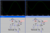
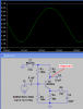
oh and this is the circuit
**broken link removed**
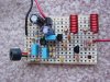
and a picture
**broken link removed**
it works great even so there is some noise and im no sure about the range of the transmitter.
Also when i removed the coil from the circuit there was no difrence in any way from with the coil and W/O the coil.
I think the noise is being caused by the face im using just random(with the correct values) caps the circuit did say use 1% low noise caps but i don't i have any of those so i just used any kind of cap i had.
I think i didn't do the coil right...
Is the coils purpose to like lower the noise in the transmittion?
oh and this is the circuit
**broken link removed**
and a picture
**broken link removed**