Continue to Site

Welcome to our site!

Electro Tech is an online community (with over 170,000 members) who enjoy talking about and building electronic circuits, projects and gadgets. To participate you need to register. Registration is free. Click here to register now.

  • Welcome to our site! Electro Tech is an online community (with over 170,000 members) who enjoy talking about and building electronic circuits, projects and gadgets. To participate you need to register. Registration is free. Click here to register now.

Fine tune step motor control

Status
Not open for further replies.

spirosd

New Member
Hello all,

I would like to control the speed of a step motor. Having done some RTFM, I have successfully used PWM to overvoltage the motor and I am now looking into slowly increasing the frequency of the steps.

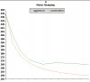
Keeping to simple math, best results are obtained from using a formula of the sort
Code:
y = x + [(2*x) / (4*n+1)]
where x is a base delay between stepping and n is the number of steps that have been completed so far.

Now, the addition is ok (addwf) and multiplication by the constants is ok (rlf), it's the division that has me stumped (I have only in the past couple of months started using asm). I have trawled through the sample code graciously maintained over at piclist.org, and everything is for 16 and 32bit variables. I am using a clock pulse to determine the delay and anything over 8bit accuracy is overkill.

Any pointers as to how to approach this division?

Thanks for your help.
Spiros
 
If you're dividing by a number 2^n then you can just shift right by n. So you should try to use 2,4,8,16, etc as a divisor if at all possible.

Dan East
 
You didn't mention the PIC family you're using. I would recommend you use the PIC18 family. They have the hardware multiply instructions. This will allow you to multiply the reciprocal of the divisor.

Division by N is equal to multiply by reciprocal R and then divide by 256.

The reciprocal values of 8-bit divisors (1-256) can be stored in a short 256 byte long table.
 
I fail to see the need for the maths really?, driving a stepper motor with a PIC is a nice and simple procedure - if you feel that formula might help in some way?, then do the calculations on a PC and just store the results in the PIC, a simple lookup table would then do all you need.
 
You are probably better of using a lookup table. But, if you want to do the maths here's a 8bit by 8bit divide.

Code:
                movlw   .234
                movwf   AccLo
                movlw   .10
                movwf   Divisor
                call    Div8by8
Hang            goto    Hang

Div8by8         clrf    AccHi
                clrf    Answer
                bsf     STATUS,C
                rlf     Answer,F
Div8Loop        rlf     AccLo,F
                rlf     AccHi,F
                movfw   Divisor
                subwf   AccHi,W
                btfsc   STATUS,C
                movwf   AccHi
                rlf     Answer,F
                btfss   STATUS,C
                goto    Div8Loop
                return

The above does 234/10 to give 23 in Answer and 4 (the remainder) in AccHi. It takes about 80 cycles.

HTH

Mike.
 
Dan East said:
If you're dividing by a number 2^n then you can just shift right by n. So you should try to use 2,4,8,16, etc as a divisor if at all possible.
Unfortunately that is not the case. If only things were that simple!

motion said:
You didn't mention the PIC family you're using. I would recommend you use the PIC18 family. They have the hardware multiply instructions. This will allow you to multiply the reciprocal of the divisor.
Ooopss, (mental note, mention the pic family next time), using 16f628a / 16f6877 not able to take advantage of those instructions. Interesting thing to know, thanks.

Nigel Goodwin said:
I fail to see the need for the maths really?, driving a stepper motor with a PIC is a nice and simple procedure - if you feel that formula might help in some way?, then do the calculations on a PC and just store the results in the PIC, a simple lookup table would then do all you need.
Yes it would be the simplest way of doing it. My only concern are changes to this table as a result of tweaking the step frequency of the motor under load, real world conditions. Too many inputs ... argghhh

Pommie said:
You are probably better of using a lookup table. But, if you want to do the maths here's a 8bit by 8bit divide.
Thank you for the leg up.

I agree that not doing the math is the prefered solution to the requirement (ramp the speed of the motor). How does it go "Keep It Simple Stupid"! At least now I know how to do an 8bit division if I really have no other option.

Thank you all for your generous help.
 
i was using steppers before but i'm confused by the formula.
where did you get it from and are you sure Y is frequency?
is X varied too or it is constant? did you check what graph of
this function looks like? assuming fixed X for simplicity,
it must have big disturbance around 0 while sides get pretty flat
only few steps away from zero. imho this formula leads to dead end
unless there is something you didn't mention.
to run stepper at higher speeds one has to ramp up speed (freq.)
and when close to target slow down. that lools like trapezoid
which is very different from what your formula would produce.
am i missing something?
 
panic mode said:
i was using steppers before but i'm confused by the formula.
where did you get it from and are you sure Y is frequency?
is X varied too or it is constant? did you check what graph of
this function looks like? assuming fixed X for simplicity,
it must have big disturbance around 0 while sides get pretty flat
only few steps away from zero. imho this formula leads to dead end
unless there is something you didn't mention.
to run stepper at higher speeds one has to ramp up speed (freq.)
and when close to target slow down. that lools like trapezoid
which is very different from what your formula would produce.
am i missing something?

Hello,

Yes I have graphed it (see attached image). The formula above corresponds to the orange line (what I named aggresive). I am not sure where I picked it up from ... trawling through the internet on a google search. The numbers on the Y axis represent the delay between each step (Y in the formula above), and on the X axis the numbers of steps (I only graphed 12 steps to indicate what would happen in the second scenario).

Y is the delay between each step
X is a base 'smallest' delay between each step (constant)
N is the number of steps that have been taken (varies)

So, we start with a slightly larger delay between steps and then progressively shorten the delay, increasing the step frequency, motor goes faster. A comparison is made such that, if Y < X, X is used as the delay. Complimented with overvoltage and PWM there is no disturbance. You do need however to 'tweek' the X value, especially under load, to ensure you are not pushing the motor.

The green line is the scenario that you outlined and it involves more than basic math. As it is more complicated, you can appreciate why it is not used.

I have implemented the suggestion by Nigel and Mike(Pommie) and used a table instead of doing the calculation. It has involved reprogramming the pic a couple of times .. but K.I.S.S.

Hope that helps to clarify.
 

Attachments

  • motor_ramp.jpg
    motor_ramp.jpg
    47.7 KB · Views: 552
spirosd said:
The green line is the scenario that you outlined and it involves more than basic math. As it is more complicated, you can appreciate why it is not used.

I have implemented the suggestion by Nigel and Mike(Pommie) and used a table instead of doing the calculation. It has involved reprogramming the pic a couple of times .. but K.I.S.S.

If using a table (which is by far the most sensible solution!) there's nothing to stop you using the more complicated option - it makes no difference to the PIC, it still just reads from a table.

You could even read the table values off the graph you posted?.

Quick thought! - you could implement BOTH types of table, and select between them using a PIC pin and switch (or some other method)?.
 
Nigel Goodwin said:
If using a table (which is by far the most sensible solution!) there's nothing to stop you using the more complicated option - it makes no difference to the PIC, it still just reads from a table.

Yes true, the formula used to graph the green line needs to know how many steps you are going to step in advance (I put 12 there for the graph). The table size is dependant then on the number of steps. Add any sort of gearing to the motor and poof ... the table could potentially be large.

This is the reason for going with the `simpler` formula, as it is easier to work with (creating a table and such, lesser of two evils ...).
 
spirosd said:
Yes true, the formula used to graph the green line needs to know how many steps you are going to step in advance (I put 12 there for the graph). The table size is dependant then on the number of steps. Add any sort of gearing to the motor and poof ... the table could potentially be large.

I suspect there's probably only a small number of values that will have any effect? - it's a mechanical system, and making small percentage changes probably won't make any measurable change. But you would have to run tests to see what changes are worth while - which is probably a good idea anyway?.
 
Status
Not open for further replies.

Latest threads

New Articles From Microcontroller Tips

Back
Top