Electro Tech is an online community (with over 170,000 members) who enjoy talking about and building electronic circuits, projects and gadgets. To participate you need to register. Registration is free. Click here to register now.
Welcome to our site! Electro Tech is an online community (with over 170,000 members) who enjoy talking about and building electronic circuits, projects and gadgets. To participate you need to register. Registration is free. Click here to register now.
Yup. THe only reason a linear regulator might be used after a switching converter is because the switching converter was too noisy or the transient response was too slow for the application . But you can also fix that by adding more output filtering.
If the purpose of the 7805's is to "clean up" the output of the switcher, you could set the switcher to 7.5V out and then nothing gets hot. In my simulations, the switcher chip itself gets to 83c which isn't bad nowadays.
If the purpose of the 7805's is to "clean up" the output of the switcher, you could set the switcher to 7.5V out and then nothing gets hot. In my simulations, the switcher chip itself gets to 83c which isn't bad nowadays.
the closer to the input voltage that my output voltage is, the less heat would be generated by the switcher, then i could use the 7805s to take the voltage down.
it would be sacrificing efficiency for better heat distribution, but i could keep my efficiency and better heat distribution by adding a heat sink.
edit:
simulation shows the temp to be the same no matter if its stepping it down to 35V or 5V.
its still putting out 2 Amps, so that makes sense.
Lower DCR is preferable, but to be honest...it doesn't really matter as long as it's not outrageously high. The buck converter feedback will just up it's duty cycle to compensate for the extra loss and voltage drop.
what would be the best way to separate the usb devices?
id like to have it so that each port only sees 500mA, instead of all of them seeing 2 Amps. that way if a device is damage or shorting its not going to go nuclear.
i was thinking... the buck takes it down to 7V, then LM7805's to seperate the devices, but the 7805's will go up to 1 Amp output if they can.
1. Use the fastest acting fuse you can find- one for each device.
2. If you are using linear regulators as the final output stage, just find a linear regulator that has current limiting set at 500mA and use one for each USB device. The REG103 for example.
Hint: The current limiting value in a linear regulator is usually what makes it "500mA", "1A", or "2A", etc. After finding one, check the datasheet of a linear regulator labelled as such and look at the current limiting threshold to confirm. THe REG10x series for example, is basically the same silicon die with different current limiting values. The lower limit devices tend to come in smaller IC packages since they are expected to dissipate less heat, but you can find 500mA and 1A devices that both share the same package with different limits that are otherwise identical.
3. Current limiting can be built into switching regulator which will lower the voltage if the current exceeds the limit in order to keep the current at the limit (things like motors will keep running with reduced power, but most electronic circuits will simply stop working because the voltage is too low). This would require current limiting in the feedback loop of the buck converter...and would require a separate buck converter for every USB device.
THose aren't fuses per se. THey are like self-reseting fuses. PTCs (Positive temperature coefficient) are like resistors that will rapidly increase their resistance after they heat up past a certain point (due to current or ambient temperature or whatever) behaving kind of like a fuse. NTCs (negative temperature coefficient) do the opposite (decrease resistance as they heat up).
Current hold is the highest current level before the resistor starts to change a noticeable amount. Current trip is when the resistance is high enough to really start affecting things, and current max is when it's really high. Something like that. You can google around for more specific info.
I'd go with an ultra-fast fuse though. I believe they are faster and more accurate (and I know they're cheaper). I would suspect an NTC might not be fast enough to protect the electronics.
You wanted a fuse to protect the system from design/assembly haywires so the point is to protect the devices it is connected to to prevent any problems from getting out of hand. The point is not to plug it in again when it fails and hope it works, or to protect from expected operational surges and then recover on it's own. You would hunt down the problem, fix it, then replace the fuse. THat's why replacing the fuse isn't that big a deal. If the fuse blows, it's an indicator of a bigger problem that needs to be fixed before the fuse is replaced.
It's like people who hit the hair dryer when it overheats and stops working in order to prematurely reset the thermostat switch so they can continue using it right away.
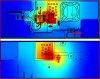
that is the heat simulation for the setup id be using.
but the sim is usually there pre made boards, and its double sided.
since im building this on the same board as the rest of my parts, ill be doing the board myself, and if possible single sided, so i wont have the extra copper traces all over the back for extra head dissipation (as does the pre made board).
This site uses cookies to help personalise content, tailor your experience and to keep you logged in if you register.
By continuing to use this site, you are consenting to our use of cookies.