Continue to Site

Welcome to our site!

Electro Tech is an online community (with over 170,000 members) who enjoy talking about and building electronic circuits, projects and gadgets. To participate you need to register. Registration is free. Click here to register now.

  • Welcome to our site! Electro Tech is an online community (with over 170,000 members) who enjoy talking about and building electronic circuits, projects and gadgets. To participate you need to register. Registration is free. Click here to register now.

Film resistor vs Carbon resistor.

Status
Not open for further replies.

gary350

Well-Known Member
Is there any reason I should not pic film resistors over carbon resistors?

Film resistors are always 1%

Carbon are always 5% or 10% or 20%

I need 240 ohms. 1/4 watt should work ok but I want 1/2 watt.

I am building 2 matched circuits. Last time I bought a 50 pack of carbon resistors testing them all with the meter there was nothing within 18 ohms of each other. I had to parallel/series 4 resistors to get within 1 ohm of target 240 ohms.
 
You also have carbon film and carbon composition.

Metal film generally have less thermal noise, but they don't destruct nicely. They "puddle".
Metal oxide tends to burn cleanly.

Here's a carbon film 5%. https://www.mouser.com/ProductDetail/Ohmite/OK2725E-R52/?

One "trick" if you just need one is to buy a larger wattage and get out the file.

Curiously, did you do a 4 terminal measurement for your final resistance?
 
I am building 2 matched circuits. Last time I bought a 50 pack of carbon resistors testing them all with the meter there was nothing within 18 ohms of each other. I had to parallel/series 4 resistors to get within 1 ohm of target 240 ohms.

5% of 240 should be within 12 Ohms.
Usually all the ones I buy are Easily within tolerance.
And Buying a 1/2 watt Won't increase the tolerance unless you need the wattage.

How Old am I?:D
I Remember when Pretty Much, All Resistors were either 10% and 20%.
Don't recall any 5% ones, back than.

KISS.......A 4 terminal Ohmmeter is not needed for such a high resistance.
 
Not clear. He wants it within 18 ohms. He's already lost 1 or 2 with leads. My picky bran sees that 240+18 and 240-18 as not being 18. Some part of that 18 is uncertain based on meter leads. 17-19 maybe? Generally you would use a 4-terminal ohmmeter, but his +-18 has more uncertainties. 18 ohms you might.

chemelec said:
I Remember when Pretty Much, All Resistors were either 10% and 20%.

True.
 
Is there any reason I should not pic film resistors over carbon resistors?
Film resistors are always 1%
Carbon are always 5% or 10% or 20%

Film resistors are available from 0.1% to 10%. Carbon resistors are available at 2% and 1%.

As for reasons - depends on the application. Carbon composition resistors have much lower inductance that equal-sized carbon film and metal film parts, so carbon comp is preferred in many RF applications. They also tolerate overpower situations better.

ak
 
Not clear. He wants it within 18 ohms. He's already lost 1 or 2 with leads. My picky bran sees that 240+18 and 240-18 as not being 18. Some part of that 18 is uncertain based on meter leads. 17-19 maybe? Generally you would use a 4-terminal ohmmeter, but his +-18 has more uncertainties. 18 ohms you might.
True.


I bought a pack of 50 carbon resistors. I tested them all with my digital meter. The value is suppose to be 240 ohms but the meter says, none are 240 ohms. Most of the resistors are on the LOW end and HIGH end but not many in the middle near 240 ohms. Low end is 216 ohms and high end is 264 ohms. There is a very large range of values so I soldered a 261 ohm is parallel with a 222 ohms this gives me 120 ohms. I soldered 259 in parallel with a 224 this gives me 120 ohms. I soldered both of those 120s is series it should be about 240 ohms and the meter says 24o for this group of resistors and I have 241 ohms on another group or resistors.

1/4 watt resistors seem to be fine for pin 1 I just thought I would play it safe and use 1/2 watt resistors.

I am turning the mosfet ON/OFF manually with 2 power supplies and a load on the work bench just to test and see what is going on. Voltage to pin 1 is 11.8 VDC. Voltage to pin 2 is 21.0 VDC. These are no load voltage readings.

The original circuit drawing calls for a STP40NF10 using a 220 ohm gate resistor but the mosfet over heat and go up in smoke pretty quick. A larger 240 ohm resistor solves the mosfet smoke problem. Mosfets still get very hot and can not be ON more than 30 seconds or they burn up.

Now I am experimenting with a P55NF06L. I was told Mosfet resistance is lower so it wont get hot as quick as the other mosfet and that turns out to be true. I am still using the 240 ohm gate resistor.

I have several items for a mosfet load, DC motors, light bulbs, hot water heating elements. If I replace the fixed resistor a variable resistor it makes a nice variable speed control for the motor and light dimmer.

The mosfits do not seem to be turning completely off with a resistor less than 240 ohms.

At my age 65 my brain does not soak this up into memory like it did when I was young tooking electronics in college. I have to make good notes to refresh my memory next week about the experiment's that I did today, that is very frustrating.
 
Last edited:
If your gate resistors are going up in smoke, then there is some serioius problem with the design or execution. Can you show the schematic?

As for the values, it is very typical that manufacturers test all their resistors and those that are 1% off end up in the 1% bin, the rest is then tested further, which explains the hole right around the correct value.
This possibly may not true for chip resistors beacuse I would guess the process is a lot tighter and they are so many of them that testing each one would not be profitable.
 
gary350: Gate Resistors on a Mosfet Should NEVER GET HOT.
The Gate Voltage is MOSTLY JUST A VOLTAGE WITH VERY LITTLE CURRENT.

Show us your CIRCUIT!
 
If your gate resistors are going up in smoke, then there is some serioius problem with the design or execution. Can you show the schematic?

As for the values, it is very typical that manufacturers test all their resistors and those that are 1% off end up in the 1% bin, the rest is then tested further, which explains the hole right around the correct value.
This possibly may not true for chip resistors beacuse I would guess the process is a lot tighter and they are so many of them that testing each one would not be profitable.


Gate resistors are not going up in smoke and not even getting warm. I worry 1/4 watt is too small. Data sheet says use 1/2 watt resistors.
 
The original circuit drawing calls for a STP40NF10 using a 220 ohm gate resistor but they over heat and go up in smoke pretty quick. A larger 240 ohm resistor solves the smoke problem. Mosfets still get very hot and can not be ON more than 30 seconds of they burn up.
This seemed to me that it is the resistors that are smoking, but nevermind.
All I can do for you is ask you once again, can you show the diagram of your circuit? Guessing stays fun only for so long.
 
YES, LET US SEE YOUR SCHEMATIC!

I have Never used a 1/2 watt resistor to drive the gate of a Mosfet in my entire life.
Just 1/4 watt resistors.
And Why the Need for a Precise 240 Ohms?
 
...The original circuit drawing calls for a STP40NF10 using a 220 ohm gate resistor but they over heat and go up in smoke pretty quick. A larger 240 ohm resistor solves the smoke problem. Mosfets still get very hot and can not be ON more than 30 seconds of they burn up..

From the symptoms you describe- gate resistors overheating and MOSFET not turning off completely- it sound like your MOSFETS are oscillaating at a high frequency. Because of the MOSFETs high frequency response and huge parasitic capacitors this is relatively common. The normal way to stop oscillations is to connect a 10 Ohm to 470 Ohm resistor right on the gate pin. This resistor is known as a gate stopper. It is also good practice to put a 220n nF upwards solid capacitor phsically between the source and drain. Also, it is unadvisable to have long leads or PCB traces on any of the three terminals (S.G.D) without taking measures to stop oscillations. Film resistors compared to solid composition resistors would make oscillation more likely but not by much, so using film resistors would be OK.

I have just seen some of your Photobucket images- amazing! Going by those images I would guess that you are into the heavy end of electronic engineering. I would thus say that your best resistor would be tin oxide. They a favoured by the military because they are rugged and will take quite a bit of abuse and the values are available in 2%.
 
YES, LET US SEE YOUR SCHEMATIC!

I have Never used a 1/2 watt resistor to drive the gate of a Mosfet in my entire life.
Just 1/4 watt resistors.
And Why the Need for a Precise 240 Ohms?


The reason I want 1% resistors on parallel mosfets is I want all the mosfets to be putting out the same power. If resistors are off 10% power will be off about 10% too. If I turn the power up to 10 amp on one mosfet the other mosfet will be different amps. 10 mosfet in parallel with random resistors output of each mosfet could be 9, 8, 11, 10, 9, 11, 8, 12, 9, 10, amps each mosfet.

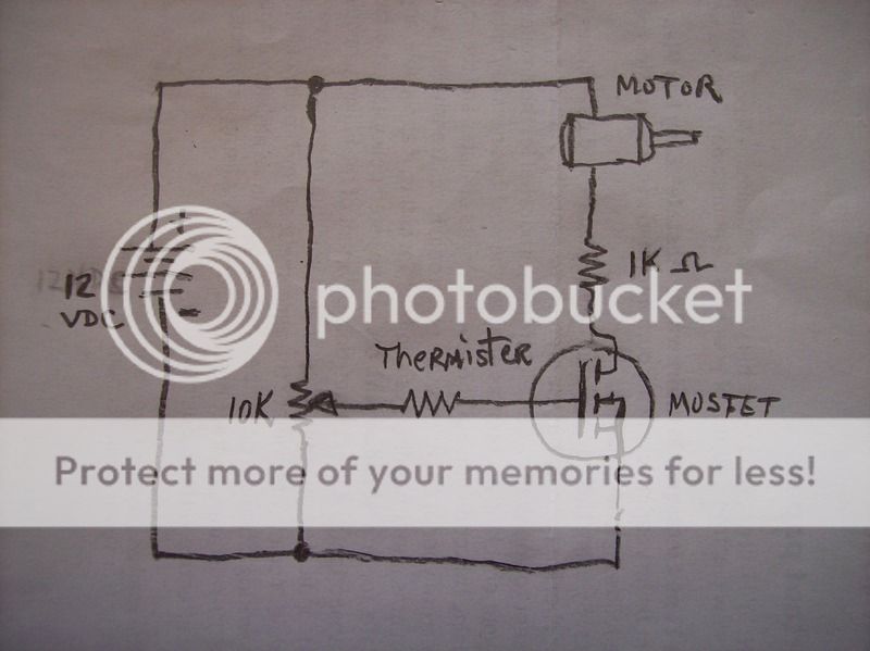
This is 1 circuit I have been experimenting with. I will have to look for the others they are mixed in with other papers. I tune the resistor to turn the mosfet completely ON and completely OFF. I can use the meter to check voltage at pin 1 when mosfet is off and on. Disconnect power supply then check resistance on pin 1 to learn what it takes to make a certain mosfet be full on and full off or full off and 35 amps full on. This was the basic circuit I started with that I made changes to it. I don't have any thermistors.

I have more than one mosfet project. This is the one I want to us to run a 5 hp fork lift motor. I have a car battery and starter solenoid connected to the DC motor. Turn on the switch it is 100% uncontrollable power. The Go Kart peals the tires like a race car and the Mini Bike is impossible to hold on. I need enough mosfets in parallel to turn the motor on slow. The Go Kart is fun like it is it goes to full speed 30 mph in about 5 seconds. The mini bike requires a momentary on switch push the button and the mini bike is gone and your not. LOL. This is so funny to watch people try to hang on but they can't. I need to make a video of this. There is no tag on this 5 HP fork lift motor I'm not 100% sure what the current is. I am not 100% sure this is 5 HP I compared it to a known motor that is the same physical size as a 5 hp. I need to put the amp meter on the go cart to see if I can get a good accurate amp reading but first I figure I will do the easier part first see if I can make mosfets in parallel work before doing anything else. The mosfets I have now are cheap $10 for 20 mosfets, 55 amps x 20 = 1100 amps. If I can only go to 35 amps each that is 700 amps. If I have the correct number of mosfets amps will be low maybe 35 amps each. OH, I just remembered something, amps will be high only on high torque take off picking up speed but not with the motor running full speed.

I found this circuit online I think it is for a toy motor. Like I said already I changed this circuit this was the basic circuit I started with. This was the original idea for the fork lift motor speed control.

007_zpsgmojvdb6.jpg
 
Last edited:
The reason I want 1% resistors on parallel mosfets is I want all the mosfets to be putting out the same power. If resistors are off 10% power will be off about 10% too. If I turn the power up to 10 amp on one mosfet the other mosfet will be 9 amps.
If the gate resistors are in series with the gates of the parallel MOSFETS, the rseistor values will not affect the voltage on the gate of the MOSFETS, which in turn affects the current the MOSFETS take.

By the way, it is not possible to put MOSFETS in parallel and have them share the current, especially the vertical types which the high current MOSFET all are. Unless you have some current sharing external circuit you need to put very low and equal value resistors in the sources of all the parallel MOSFETS.

Although you have not replied to my request for information at the other thread on this topic, it seems almost certain that you are stressing the MOSFETS beyond their capability. The data sheet maximum current of 50A means nothing in itself; it is just specmanship. You need a design to solve your problems. Such a design would be simple to impliment, but I for one, would need more data about your set-up to suggest a solution.
 
Last edited:
The reason I want 1% resistors on parallel mosfets is I want all the mosfets to be putting out the same power. If resistors are off 10% power will be off about 10% too. If I turn the power up to 10 amp on one mosfet the other mosfet will be 9 amps.

This is 1 circuit I have been experimenting with. I will have to look for the others they are mixed in with other papers. I tune the resistor to turn the mosfet completely ON and completely OFF. I can use the meter to check voltage at pin 1 when mosfet is off and on. Disconnect power supply then check resistance on pin 1 to learn what it takes to make a certain mosfet be full on and full off. This was the basic I started with that I made changes to. I don't have any thermistors.

007_zpsgmojvdb6.jpg

How are you going to get 10 A through that circuit at 12V with a 1K resistor in series? That isn't going to happen. Why aren't you using PWM

John
 
The P55NF06L can hold 60V when it is compeltely off, and allow through 55A when it is turned completely on. Anything in betweeen will produce great power dissipation in it and it will get very hot, just like a resistor would. If you want to use it like this to limit the current, then you need a very large heatsink.
 
Gary,

Here is an outline circuit that will do your job now that you have provided the information requested. Three parallel MOSFETS are shown but the number required will depend on the maximum current that the motor takes.

As jp said you will need to use pulse width modulation, but that is no big deal ... famous last words!

Just two more bits of info required:
(1) What is the maximum current the motor takes when it is running flat out undrer full load?
(2) What is the motor start current when under full load?


ETO_2015_12_14_MOSFET_02.png

 
Last edited:
The P55NF06L allow through 55A when it is turned completely on.

jp I think 55A is asking a lot when all the practical considerations are taken into accout. It may handle 55A for a few a few miliseconds, but I doubt DC, especially in a a TO-220 case. There is also the long-term reliability to consider.
 
Last edited:
No it won't, not more than a few miliseconds anyway, and in a TO-220 case even that is debateable.
Not according to the previously cited IR document:
upload_2015-12-14_18-49-18.png


Can you support your spec_ulation with similar data?

John
 
Status
Not open for further replies.

Latest threads

New Articles From Microcontroller Tips

Back
Top