Continue to Site

Welcome to our site!

Electro Tech is an online community (with over 170,000 members) who enjoy talking about and building electronic circuits, projects and gadgets. To participate you need to register. Registration is free. Click here to register now.

  • Welcome to our site! Electro Tech is an online community (with over 170,000 members) who enjoy talking about and building electronic circuits, projects and gadgets. To participate you need to register. Registration is free. Click here to register now.

Fets and transistors get hot and blow up

Status
Not open for further replies.

triple_access

New Member
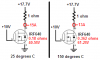
i find it funny the 2n3055 is rated at 15 amps and irf640 about the same...

i cant seen to get a good amp outta either one of them!

am i doing something wrong? why do they get so hot when only using 12volts 1 amp? both of them have high current ratings when not pulsed, so what is my problem?

according to the pdf's the current is good, but when i get them here i cant get one amp outta them?

is there a certain way you have to turn them on or something?
 
Some thoughts:

A. Are they attached to a proper heat sink?

B. Are you sure about your measurements - assuming that you've addresses the heat sink issue?

C. Are you sure you've obtained good parts?

Can't offer much more with so little information.
 
well i was using the FQA30n40 fet witch is about a 400v 30 or so amp fet, i used this to run the stator on an alternator from around 2 to 8 amps, witch i hardly ever use 8 amps. it stoped working like all the others over a period of time.

i was using a 555 timer to pulse the fet to regulate the needed output to the stator, but i soon seen i did not need pulses that i could make the circuit smaller by just regulating the voltage and amperage, with 1 to 2 amps is ideal.

so my good fet is now dead.


i have 5 irf640's laying around.

what i have done, i have taken a 3 pin pot and added 2 100 ohm resistors on the outer side of the 50k pot, i hooked the gate of the irf640 to the center of the pot.

ground the source of the fet, and the rotor goes between the Drain and + side of the battery.

i turn the pot and read that i am pulling .40 amps with the stator and the fet starts to heat up, if i go to .70 amps it will burn my finger and i cut it off.

so why is this 18 amp fet or so not handling this small 1 amp? i do not know.

i have seen a circuit from **broken link removed**

they say it can produce 15 amps, man i've blowed many of those at just .70 amps, i don't understand how everyone is getting all these amps outta these chips when i cant?
 
How did you determine the size of the heat sink? What case temperature were you expecting - given the heat sink and related conditions?
 
FETs like to be on or off. That is why they are usually pulsed. Being partially on strains them.
 
The pulsed vs continuous operation may be where the OP is getting into trouble. Heat sink requirements are eased if pulsed.
 
i guess that about sums it up, i had my fet in stress with that pot..

but i was still wondering, i use to drive a 2n3055 with a 555 timer, still i couldn't get 1 amp outta it, maybe i was using the wrong frequency?

or just mabe i didn't have it hooked properly?

i had the base going to the gate, there where 2 resistors at the pulse of the gate to = everything out.

the emitter was grounded, then the load was between the collector and + 12 volts. smoked several at 1 amp so i just didn't buy anymore because i felt they where crap.

if i could get 15 amps or any thing close to that from a cheap 2n3055 it would be a dream.

thanks much.
 
I am far from being the expert here but it seems unlikely that a 555 could deliver enough current - never mind the frequency. You might need several amps applied to the base of the 2N3055 to get anything close to 15 amps out of it.
 
ahh, so thats what i've been doing wrong! thanks you,, lol i feel stupid..

i cant understand them crazy pdf's or i would have known that.
 
I hope you are kidding about feeling stupid. At least you are exploring, experimenting and learning.

I recently constructed a regulated power supply with an 2N3055 as the output transistor - simply because I have lots of them. I drove the 2N3055 with an LM317. You might construct something like this then make some measurements of the base current and collector current as a way of measuring the gain of the transistor under those conditions.

A person who serves as a mentor to me (electronics is my hobby) pointed out that the current gain of garden variety 2N3055s can be very low and is quite variable from transistor to transistor - something like 10. That suggests that for 15 amps out I need to drive the base with 1.5 amps. The numbers may be wrong but I think I am illustrating the point sufficiently.
 
Don't guess, look at the datasheet for a 2N3055.
It is not spec'd at 15A. It is spec'd up to only 10A.
Its minimum current gain at 10A is 5. Then its base current is 2A.
Its max saturation voltage loss is 3.0V at 10A when its base current is a whopping 3.3A. Then it heats with 38W max, 30W at the collector and 8W at the base.

The IRL640 has a max on resistance of 0.18 ohms when its case is somehow held at 25 degrees C. If it saturates with 15A then it heats with 40.5W max.
The heat causes its resistance to rise which makes it hotter which causes its resistance to rise more which .......

Power dissipation (heat) is the current through a transistor times the voltage across it. If it is turned on hard, then the voltage across it is low and it won't be too hot.
 
audioguru said:
Don't guess, look at the datasheet for a 2N3055.
It is not spec'd at 15A. It is spec'd up to only 10A.
Its minimum current gain at 10A is 5. Then its base current is 2A.
Its max saturation voltage loss is 3.0V at 10A when its base current is a whopping 3.3A. Then it heats with 38W max, 30W at the collector and 8W at the base.

The IRL640 has a max on resistance of 0.18 ohms when its case is somehow held at 25 degrees C. If it saturates with 15A then it heats with 40.5W max.
The heat causes its resistance to rise which makes it hotter which causes its resistance to rise more which .......

Power dissipation (heat) is the current through a transistor times the voltage across it. If it is turned on hard, then the voltage across it is low and it won't be too hot.

The rise in resistance doesn't make it hotter because that decreases the current and hence the dissipated power. This is why you won't find a second breakdown curve in the SOA of a power mosfet. Just so the learning OP isn't confused by this ominous statement.
 
The rise in resistance doesn't make it hotter because that decreases the current and hence the dissipated power. This is why you won't find a second breakdown curve in the SOA of a power mosfet. Just so the learning OP isn't confused by this ominous statement.


This is a little misleading as well… for example take 10V source connected in series with a 1 ohm resistor and MOSFET (I know… this is just a heater). Let’s say the MOSFET has an Rds on of .01 ohms at 25°C. The power dissipated by the MOSFET would be ~1W (.98W) (I^2*R). If for any reason the MOSFET’s on resistance increases (temp affects, biasing etc.) and triples to .03 ohms, the power now dissipated in the MOSFET has increased to ~3W (2.82W). So even if the Rds on increased by 300%, it did little to reduce the current flowing through it, but the power the MOSFET has to dissipate sure goes up.
 
Optikon said:
The rise in resistance doesn't make it hotter because that decreases the current and hence the dissipated power.
No.
The datasheet has graphs that show the on-resistance doubles from 25 degrees to 150 degrees C. Then in my example with a 15A load, the current drops to 13A when the Mosfet is hot but its dissipation increases 51%.
 

Attachments

  • Mosfet thermal runaway.PNG
    Mosfet thermal runaway.PNG
    7.1 KB · Views: 332
audioguru said:
No.
The datasheet has graphs that show the on-resistance doubles from 25 degrees to 150 degrees C. Then in my example with a 15A load, the current drops to 13A when the Mosfet is hot but its dissipation increases 51%.

VERY unusual if this FET has a positive TCR of resistance.. the OP should get a real power mosfet instead of a strange device.

There should be a second breakdown spot on the SOA curve in that daatsheet then as well.
 
You can connect Mosfets in parallel because their on-resistance increases when they get hot. The opposite of junction transistors.
 
VERY unusual if this FET has a positive TCR of resistance..
Please cite some "real power mosfets" with zero or negative TCR.

I've only seen power mosfets with a positive TCR.
 
mneary said:
Please cite some "real power mosfets" with zero or negative TCR.

I've only seen power mosfets with a positive TCR.

I dont believe there are any.. what I mean to point out is.. when a MOSFET on resistance increases *and* causes MORE power dissipation which then further increases the on resistance.. this is thermal runaway and the part will self destruct. Audio guru was pointing this out.. yet, there is no 2nd breakdown area in the SOA...why not??? Usually the positive TCR keeps this from happening.. Audio's original comment made it sound like that is not the case.... This is what I find strange.
 
The power dissipation in the Mosfet is maximum when its resistance equals the load resistance. When its resistance increases above the load's resistance then its power dissipation becomes less.
 
Status
Not open for further replies.

Latest threads

New Articles From Microcontroller Tips

Back
Top