Continue to Site

Welcome to our site!

Electro Tech is an online community (with over 170,000 members) who enjoy talking about and building electronic circuits, projects and gadgets. To participate you need to register. Registration is free. Click here to register now.

  • Welcome to our site! Electro Tech is an online community (with over 170,000 members) who enjoy talking about and building electronic circuits, projects and gadgets. To participate you need to register. Registration is free. Click here to register now.

Fax power suply

Status
Not open for further replies.

bogdanfirst

New Member
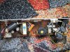
I have a fax power suply wich seems to have burned out.
first, there is the transistor, as 2SK727. the resitance between pins is 0.1 ohm between the outer most pins of the case, and about 16 ohm between each of those and the center pin.
i don't think this is righ, or is it? i mesured the transistor outside of the circuit(removed it)
also, there are some leaking filter caps wich i will replace, 1000uF/35V, two of them, and another 1000uF/16V.
the suply comes from a Schneider SPF 402 fax.
does anyone know the voltages it should output? and can i use it for something.
i think it outputs 24V and 5V for sure. the steppers are 24V, though there is something strange about them. on one of them says 'made in japan' and on the other is says 'made in china'. the both look identical and have the same characteristics.
i will attach the picture of the suply. maybe someone can help me with the schematic for it?
thanks!
 

Attachments

  • img_9502___22.jpg
    img_9502___22.jpg
    179.8 KB · Views: 802
The 2SK727 is a FET. Measuring them can be trickky sometimes, your meter itself may put it into a conductive state making it look shorted...
perhaps a mosfet expert can shed more light on this...
 
well i tested it both with the ohm meter and with the conductance tester on my multimeter.
the thing is that it conducts both ways....it shouldn't do that.
plus, i replaced the burned fuse, plugged it in and the fuse blew up....all it remained were the metal ends.

maybe i am wrong.....and it should be that way.
 
I'd say the FET is shorted. First thing I ususally check in any dead PSU that blows fuses hard, is usually a dead shorted power transistor on the primary side of the switching transformer. It could also be a shorted primary cap, so check those too, since you said you had a leaker or 2.

Not much else on the PCB can take out a fuse like that without showing signs of losing the war.

Usually good practise to change out all the filter caps also. they tend to develope high ESR ( equivalent series resistance ) with age, and this causes more problems with what ever is connected to the supply, due to the ripple.
 
yes, that's what i think too.
the transistor is shorted.
and i removed the filter caps and will replace them. 3 of them.
do you think i should replace the big filter cap for the HV side? it's a 100uF/400V. i tested it with the multimeter. it shows 98uF, so i think it is ok.
now, a question....what could it cause the FET to short?
 
Try measuring all large resistors (not physically large, but high ohm value). They are often the cause of failure in switching power supplys
 
I would replace the large filter cap also, it may have developed a high ESR. or be leaking internally, not helping the FET in it's quest for longevity.

Sometimes the FET will just decide it's had enough, but most often it gets help in the form of a bad input capacitor, mains surge, etc. I would have a really good look at the insulating washer/thermal pad under the FET for any signs of pinholes or arcing/flash-over. Sometimes the FET can blast a small piece of metal into the thermal pad when they go bang.

Exo has a good point also, one of the high value resistors in the circuit may have opened under stress, with no physical signs. For some reason, and I have no idea why, they like to blow a piece of themselves off on the PCB side where you can't always see it. Of the times I have seen this, only once was there a trace at lower potential that the resistor had arced to, causing the failure.
 
well, I will test all the resistors and I have tested the diodes and they seem OK. I think that i will replace the filter cap as well.
still, i have one more question.....what is the rating of such a power suply.
how much current for each output?
i know it outputs 24V, probably 5V and -12V by the regulators on it(7805 and KA79M12).
 
Status
Not open for further replies.

Latest threads

New Articles From Microcontroller Tips

Back
Top