Electro Tech is an online community (with over 170,000 members) who enjoy talking about and building electronic circuits, projects and gadgets. To participate you need to register. Registration is free. Click here to register now.
Welcome to our site! Electro Tech is an online community (with over 170,000 members) who enjoy talking about and building electronic circuits, projects and gadgets. To participate you need to register. Registration is free. Click here to register now.
Are there no references? google them, try to get a datasheet, if it's a good datasheet, it should have everything, maybe even working code, as for connecting it to a computer, maybe a parallel port app should do, if not, have an MCU between the lcd and the computer.
Yeah, it is a good practice anytime to get datasheets, and the LCD would need some interfacing before you can connect it to a PC. Use PICs, they're simpler to control LCDs.
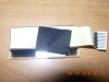
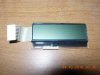
I think it is one of those "in-house" parts. Because I can't find any sort of numbers on it whatsoever. I was hoping someone would recognise the shape of it and hopefully tell me how I could use the ribbons.
I still have the board that the ribbon plugs into. Should I grab my camera...
Sparkfun has a great tut on learning C and using AVRs - he makes it easy! Now using the micros to reverse-engineer the communication, harder. Honestly, I would just buy an HD44780 LCD, or if you don't want to figure that out, buy a SerialLCD.
Sparkfun has a great tut on learning C and using AVRs - he makes it easy! Now using the micros to reverse-engineer the communication, harder. Honestly, I would just buy an HD44780 LCD, or if you don't want to figure that out, buy a SerialLCD.
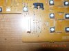
I had to stretch your picture out onto both my monitors to see it all at once, and I can't figure out that that part its! What part of the machine did it come out of? I'm thinking it was maybe a light-strip for scanning or faxing inside the machine.
AVRs and PICs are both micro-controllers. Both are very popular among engineers and hobbyists. The AVR family is made by the company Atmel. I've only ever worked with AVRs. PICs are a microcontroller family made my the company Microchip.
Here's an AtMega168: **broken link removed**
Isn't it cute?
AVRs have a wonderful development platform called Arduino. They are $30.
I never use dev boards. Just the chip on a breadboard with all it's friends.
Either are good for C. If you really want, you you can also program them in BASIC. And if you really want, you can program in Assembly too.
So if it was near the area where it scans the paper, then I'm thinking it's either a light to illuminate the paper so the scanner can see it well, or it is actually the scanner part. I have no idea how to interface with something like that however.
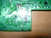
This a ccs sensor. Mostly old type scanners have of this ccs sensors. Sensors names writes behind of this sensors. You have to desolder to see the name. For lcd pin outs you need service manual of this fax machine or maybe something writing on the lcd board. code, name or so... I didnt see detail foto ot the lcd board. Maybe i could say something.
By the way, as far as the original LCD you were talking about that doesn't look like a 'module' at all, just a raw LCD display, the output pins are probably a multiplexed row/column setup for the individual elements of the LCD. It would have been easier to figure out what pin was what if you could have checked it with a multimeter or scope while it was still on. You could probably test it using a single AA battery connected to wire leads, and just start touching the pins the AA battery will provide the bias required by the LCD, though I don't think they like constant DC it's an easy way to test them. You'd have to be pretty determined to want to use that EXACT LCD from that fax machine in order to justify building an interface as I think the rest of this posts shows there are some really great modules out there that require nothing more complicated than a serial interface.
This site uses cookies to help personalise content, tailor your experience and to keep you logged in if you register.
By continuing to use this site, you are consenting to our use of cookies.

")