Continue to Site

Welcome to our site!

Electro Tech is an online community (with over 170,000 members) who enjoy talking about and building electronic circuits, projects and gadgets. To participate you need to register. Registration is free. Click here to register now.

  • Welcome to our site! Electro Tech is an online community (with over 170,000 members) who enjoy talking about and building electronic circuits, projects and gadgets. To participate you need to register. Registration is free. Click here to register now.

Farfalle: Coming soon!

Status
Not open for further replies.
S

Souper man

Guest
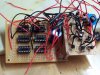
Faced by my Microcontroller problem, I needed somthing that would relieve my stress. I was thinking of cool robot Ideas using my Dual Voltage (Motors run on 3v and the circuit is powered by a 9v/other circuitry) Dual H-Bridge, and I came up with Farfalle. Farfalle is currently in the works, but Farfalle is going to be a Walking robot with slots to add stuff on to! Farfalle will be very cool, and I promise I will have pictures along with my robo-review within the next 4 days. It will be able to have "expansion slots", meaning it will be easy to add other systems onto Farfalle.

The following robots so far in order of completion

Spaghetti, a line following robot using a dual comparator.
Fettuccine, a light seeking robot based on dual astable 555's
Farfalle, a walking robot with expansion ports (COMING SOON!)

I promise, this will be cool!
 
Looking forward to it. What are you going to use for walking? Servos?
 
I am going to incorporate standard DC motors, somehow. I already have a few ideas.
One of the problems I may encounter is the Leg movement, or the feet. to convert a rotational force into a vertical motion may be difficult.
 
Last edited by a moderator:
I am having problems trying to develop the walking robot technique. I have never done this before so im going to put the walker on delay. I will however continue with the module idea, with easily interchangeable and swappable parts. I am almost done actually, and promise to get pictures up tomorrow. What kind of robot should it be? room exploring? line following?

EDIT: I have studied walking robots now for about 2 hrs, so armed with the information I ahve learned, Farfalle is going to be completed as formerly advertised!!!

Farfalle will use perhaps 2M4L setup, using run of the mill logic chips and maybe my H-bridge!

(YUMZ, LOGIK CHIPZ)
 
Last edited by a moderator:
Body Design planned out and will be put into production tomorrow, along with legs and possibly circuit.
 
I am about a quarter done with farfalle, so I decided to post some pictures!

i hacked my servo to rotate either way without PWM so I could interface it with my modified H-Bridge. I need one more servo, then Farfalle will be about half complete (along with legs). Then I will design the circuitry.

1362: The 'usual' clutter when Im designing stuff

1364: Farfalle with large 8mm UV LED in upper left corner of perf board. also includes: 5v reg, dual H-Bridge, and hacked servo in front.

1367: another view of farfalle.

1368: My brand new shiny multimeter
 

Attachments

  • 100_1362.jpg
    100_1362.jpg
    740.5 KB · Views: 272
  • 100_1364.jpg
    100_1364.jpg
    824.9 KB · Views: 253
  • 100_1367.jpg
    100_1367.jpg
    675.4 KB · Views: 244
  • 100_1368.jpg
    100_1368.jpg
    701.9 KB · Views: 278
I found the website once, but forgot what it is. Do you know?
 
Google "Tamiya Gearbox" scads of hits. They make lots of em plus wheels etc...
Your local hobby store should be able to get them for you.
 
My local hobby store (where I bought my servo) had a 2ft shelf with 2 basic electronic kits (the snap on kits, which is for 2 yr olds), and a few servos. The servos were actually well priced. They may be able to order them for me, but I dont have 0 money. My income is begging and finding/taking cans to the store for money (michigan is only state with 10 cent return, which rox).
 
Thats not bad. Our cheap servos are $13.29 (In US), so I wouldnt expect it to be much more.
 
Designed better circuit for Walking motion, using 2 AND gates, to buffer the signal to create less electrical noise, and put a NAND gate at the end to create the desired inverting effect.

Where should I place some key capacitors? I was going to place a .1uf cap across each chips power leads to lessen electrical noise, and a large cap (1000uf) across the + and - bus to lessen electrial noise and supply power when the servos kick in (which will be constant, aka walking). I also am using the 7805, so I might need some caps placed around there, but I dont know where. Any suggestions as to what size and where?
 
Last edited by a moderator:
I have soldered all of the 14pin sockets in, all 6 of them. I am going to use a Comparator to create a Little circuit that when it hits the dark threshold, it will shut the robot off. any suggestions? I also need to know where to place those caps, because I am about 1/3 the way done with my bot.
 
More Pictures of Farfalle!

This picture shows the 6 IC sockets for Farfalle, which to date is my biggest project. The top 3 IC sockets will hold 3 AND gates, which will buffer the signal for the 2 Shmitt Trigger NAND gates, which will control the H-bridge. The lower right socket is for the light control circuit, which will shut the robot off if its too dark, but I have yet to hook this up. Farfalle is not done yet, but will be by 7-16!
 

Attachments

  • 100_1369.jpg
    100_1369.jpg
    764.5 KB · Views: 252
Last edited by a moderator:
Yeah, it is pretty close to the regulator.

I revised the circuit, and I found out a way easier way of controlling the H-bridge. Im going to change up the circuit a little bit to make it more efficent (inverter oscilliators running at a very low frequency, perhaps 1 hertz).
 
Good news: I have modified the system to adapt to the easiest chip in the world... The 555! I have one 555 set up in astable mode and the other in a inverting buffer.

Circuit debugged.
Tension spring added to help center legs and keep servos from 'drifting'
Body design being designed (lol)
Leg models being modeled (lol again)
Circuit simplified.

Expect to wake up tomorrow to see a awesome walking robot!!!

I am very excited!
 
Everything is working, except for the legs. I dont know how I am going to mount them to the legs.
 
Just look at how the Parallax Toddler Robot was designed.

**broken link removed**
 
Status
Not open for further replies.

Latest threads

New Articles From Microcontroller Tips

Back
Top