Continue to Site

Welcome to our site!

Electro Tech is an online community (with over 170,000 members) who enjoy talking about and building electronic circuits, projects and gadgets. To participate you need to register. Registration is free. Click here to register now.

  • Welcome to our site! Electro Tech is an online community (with over 170,000 members) who enjoy talking about and building electronic circuits, projects and gadgets. To participate you need to register. Registration is free. Click here to register now.

Fan OK circuit

Status
Not open for further replies.

dannix

New Member
Hi,

First of all, I can build circuits but Im not the best on the design side.

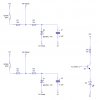
I am looking to make a circuit that monitors a fan, if it is running I want to switch a 1.5a load. I have been looking and looking and looking but all i can find is fan failed circuits like the one here:

**broken link removed**

or maybe the use of MAX6684 IC

This is a batery operated circuit so power usage to the min if possible. I considered the use of the fan signal wire to drive a mosfet but the signal is not strong enough. Any suggestions?

To understand how this is being used. I have a thermostat circuit that will provide upto 200mA, this should be enough to drive a small fan and the above monitor circuit (if not I will amend so it can provide more), when the fan is switched on the monitor circuit will turn a PTC Heater on, when the temp rises the fan turns off and thus the heater.

If the fan is damaged/rota locked then the heater will not function.


Thanks in advance
 
Just use a current sense resistor to detect the current flowing though it.

For example if your fan normally uses 100mA and you connected a 1:eek:
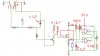
hm: resistor in series with it, you would expect to have about 100mV across it, any higher and you'd expect the fan is either jammed or short circuited, any low and it's obviously gone open circuit. You also need to add an RC circuit to fliter out any noise generated by the fan.
 
dannix said:
This is a batery operated circuit so power usage to the min if possible. I considered the use of the fan signal wire to drive a mosfet but the signal is not strong enough. Any suggestions?

The yellow or white signal wire on the 3 wire fans I have seen are simply connected to a transistor switch to ground inside the fan. This wire does not supply a voltage. To control a MOSFET, simply connect this fan wire to the MOSFET's gate terminal and add a resistor from the gate to +12V. 1K to 10K should work fine. The fan sense wire is switched to ground through the fan's internal transistor 2X per revolution. Duty cycle is about 50%.
 
Last edited:
Bob Scott said:
The yellow or white signal wire on the 3 wire fans I have seen are simply connected to a transistor switch to ground inside the fan. This wire does not supply a voltage. To control a MOSFET, simply connect this fan wire to the MOSFET's gate terminal and add a resistor from the gate to +12V. 1K to 10K should work fine. The fan sense wire is switched to ground through the fan's internal transistor 2X per revolution. Duty cycle is about 50%.

Am I right in calling that a "pull up resistor"?

Also, will that rapid switching be a problem? I don't want to loose too much juice if it can be avoided.
 
Aren't I good to you. (Attached)

Well actually, I just pulled apart my computer's fan monitor and simplified it a little. ;)

Enjoy.
 

Attachments

  • Fan Monitor.jpg
    Fan Monitor.jpg
    105.7 KB · Views: 209
Last edited:
dannix said:
Am I right in calling that a "pull up resistor"?

Also, will that rapid switching be a problem? I don't want to loose too much juice if it can be avoided.

Yes it's a pull-up resistor.

Rapid switching? I suspect that it switches many times faster than the fan could possibly rotate, even at supersonic fan-tip speeds.
 
Bob Scott said:
Yes it's a pull-up resistor.

Rapid switching? I suspect that it switches many times faster than the fan could possibly rotate, even at supersonic fan-tip speeds.

I mean for efficiency, I was told when switching the mosfet on and off, the bit between on and off wastes lots of power, this will be switching every half fan rotation. Although it will work, is it efficient?
 
yngndrw said:
Aren't I good to you. (Attached)

Well actually, I just pulled apart my computer's fan monitor and simplified it a little. ;)

Enjoy.

Thank you so much!!

So that will turn the LED on when the fan is running, can I change Q3 for a mosfet as this will run a PTC heating element at 12v 15w, or 1.25A can I use say IRF510 as I have one at home.

As this is battery operated (solar charged) I need to save juice where possible - since I now have 2 suggestions, which would be more efficient?
 
No, it will turn the LED OFF when it is running.

To invert it's operation you could remove the LED alltogether, connect the emitter to 0V, increase the size of R4 to about 10K and connect the gate of your MOSFET to the collector of Q3.

When the transistor turns on, it will pull the bottom of R4 to near 0V. When the fan is working it will be about 12V.

I don't know how efficient it would be.

Edit: I can try and work out worst case losses in the circuit, but it's a bit of a guess. Somebody correct my numbers please.

I'm assuming Vsupply = 12V and the duty cycle of the fan is 50%. I'm assuming that the circuit is used for one fan only and that a neglegable amount is lost through the capacitor.

the fan is connecting the junction between R1 and R2 to ground at a duty cucly of 50%. Therefore the power lost (Through R1) is:
P = V^2 / R * DutyCycle
P = 12*12 / 10,000 * 50%
P = 144 / 10,000 * 0.5
P = 0.0072A = 7.2mA

In adition to this, an amount is lost through R1, R2, D2 (The zener) and Q3 while the fan is in a fail condition (Neglegable while the fan is working okay. (We'll ignore D2 and Q3):
P = V^2 / R
P = 12*12 / 20,000
P = 144 / 20,000
P = 0.0072A = 7.2mA

Finally, in the inverting circuit I suggested above, we have a loss theough R4. However this loss is neglegable while the fan is working fine:
P = V^2 / R
P = 12*12 / 10,000
P = 144 / 10,000
P = 0.0144A = 14.4mA

So in total, aproximatly:
While fan is okay: 7.2mA
While the fan is in a fault condition: 28.8mA

There will also be a small loss from charging and discharging C1 in both conditions.

I guess you could increase R1 to 100K but you'd have to try it. :eek:
 
Last edited:
Wow, I was not expecting that, either you are bored or very kind!

7.2mA does not seem alot, but how would that compare to the option of using just a pull-up resistor? Since there is just the one component i would guess it is more efficient.
 
Well if the pull up resistor is 10K, it would be the same as my calculation for R1. (7.2mA)

R1 is infact a pull-up resistor. By the other option, I thought you ment Hero999's suggestion of a current sensing resistor.

In my circuit (Well the one I ripped out of my PC), the other components just smooth the signal into a nice neat transistor output.
 
yngndrw said:
Well if the pull up resistor is 10K, it would be the same as my calculation for R1. (7.2mA)

R1 is infact a pull-up resistor. By the other option, I thought you ment Hero999's suggestion of a current sensing resistor.

In my circuit (Well the one I ripped out of my PC), the other components just smooth the signal into a nice neat transistor output.

That has sold me then, thank you so much for your help -> just a few other issue to iron out then I can install it all in the shed and blow something up :D
 
Oh one other thing, is simple to latch an LED on if the fan fails? The LED would be from a seperate supply but from the same batteries, as it is in the shed and not running during the day I am unlikly to know if the fan has failed although the above circuit will ensure the heater will not operate without it. It would be nice to have an indication even if the temp is such that the fan & heater should not be running (hense seperate supply).

Again thanks alot for your help.
 
You could use an R-S latch to keep the LED on. You can build one out of a few NAND gates.

**broken link removed**
(It's active low, it also needs to be reset at startup using a capacitor because it's startup state is "undefined". I.e It could start up in any state.)

To test the circuit, if you're using a PC fan you can just remove the fan blades / magnet from the fan. This will leave a circuit board with the coils and hall-effect switches on it. As there would be no magnet moving past the switches, it's the safest way of testing for a dead fan. (You could always poke a stick into the fan to block it, but it isn't advised !)
 
Here is the amended circuit, less the LED latch - I will add that later, just to make sure I understood what you said to invert itsoperation.
 

Attachments

  • fan_signal_switch.jpg
    fan_signal_switch.jpg
    27.2 KB · Views: 168
yngndrw said:
You could use an R-S latch to keep the LED on.

it also needs to be reset at startup using a capacitor

So I could replace the reset switch with a capacitor of say 1mf???

Remove the set switch and tap off the emmitor instead for a gnd?
 
Ok, I have guessed a bit at how it should go together - Hope it is correct but to be honest, I have not got a clue lol

Attached is what I think it should be, but here is what should happen:

Fan OK: the NAND latch supply is on, the LED will be off. S1 is switched on, the fan runs, signel will operate the circuit you provided to turn on the mosfet and heater, LED remains off.

Fan Failed: NAND Latch supply is on, LED is off. S1 is switched on, the fan is damaged so fails to run, mosfet does not turn on, heater remains off, LED turns on - Temp changes and S1 turns off, LED remains ON until NAND supply is reset.

*fingers crossed*
 

Attachments

  • fan_signal_switch.jpg
    fan_signal_switch.jpg
    56.7 KB · Views: 148
Okay you're nearly there, I've made a few changes:

R5) 10K -> 100K, will give a startup time of 0.5s. Also remember that the fan needs to spin up, so you may need more than this. Could try a 1M resistor to give you 5 seconds.

C1 & C2) 1mF (milli) is 0.001F, 1:mu: F (micro) is 0.000001F - Corrected.

S1) The GND half of S1 is not needed.

R4, top) +12V supply is needed here, Q2's gate disconnected.

R4, bottom) Q2's gate connected here.

Latch) +5V supply added as that's what they work with, also means less power wasted from the LED safety resistor.

LED) Safety resistor added, value: 160:eek:hm:

Latch trigger) Moved to further back. R3 has been removed as R4 now does it's job. Also added a resistor (Marked in blue) which should be the same value as R4. This will form a potential divider to half the voltage.

Notes: Zener diode is 7.5V.
You could POSSIBLY increase R1 and R4 to 100K to save power.
You could replace the LED and safety resistor with a single 5V LED which MIGHT save a bit of power.

Hope that helps. :)

PS: Why are my email notifications not working. :(
 

Attachments

  • fan_signal_switch.jpg
    fan_signal_switch.jpg
    266.6 KB · Views: 164
yngndrw said:
Okay you're nearly there, I've made a few changes:

.....

Hope that helps. :)

"Hope that helps", that is fantastic!! I will redo it in eagle and post it here just to make sure I got it right.

Thank you so much for your help.


PS: I too am not getting email notifications.
 
Status
Not open for further replies.

Latest threads

New Articles From Microcontroller Tips

Back
Top