Continue to Site

Welcome to our site!

Electro Tech is an online community (with over 170,000 members) who enjoy talking about and building electronic circuits, projects and gadgets. To participate you need to register. Registration is free. Click here to register now.

  • Welcome to our site! Electro Tech is an online community (with over 170,000 members) who enjoy talking about and building electronic circuits, projects and gadgets. To participate you need to register. Registration is free. Click here to register now.

Fan from server how to work ?

Status
Not open for further replies.

Silverfan

New Member
hi@all

A few days ago was an old HP pro liant 740 server recycled and any part i´ve rescued. One power supply and one fan.
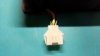
The fan was a very strong version . It use 12V an 10A for work !.
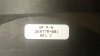
But it use an 6 pin connector .
I do not point where and what must be connected with it the fan to 12 volts can be pursued.
Any ideas ?
 

Attachments

  • 20160307_225602.jpg
    20160307_225602.jpg
    319.2 KB · Views: 302
  • 20160307_225623.jpg
    20160307_225623.jpg
    349.6 KB · Views: 315
  • 20160307_225638.jpg
    20160307_225638.jpg
    117.5 KB · Views: 284
Last edited:
I think it´s an brushless with 4 pin control.
Not an stepper motor.
old data sheets from manufacturer exist as an 12V direct version ( Beta V Series)without 4 Pin control.
But any versions exist who not exist any data sheets.
One version was an HP version ( see pics)
Support from HP give no Information over connections .
How 4 pin to works i don´t know.
 
Any ideas ?
Welcome to ETO, Silverfan!

You might be able to take it apart and get an idea of how it is, at the least, wired. This is a non-destructive tear down: the fan can be put back together.

Most fans of that sort have a hole in the middle of the back (where the paper ID sticker is). In that hole is one end of the shaft that has the fan blades on the other end.

Ordinarily you can cut out the paper covering the hole and gain access to the "circlip" (or whatever they used) the holds the fan shaft and the circular, cup magnet rotor in place. Pull on the vans on the fan to pull it out of the fan body. You should then be able to see the fixed stator coils.

This just an example. The number of coils varies.
upload_2016-3-7_18-28-25.png

You should also be able to see if there are any components in that area or if there are simply connections to the coils for the various colored wires entering the fan.

If there are components, the "chopping" of the DC power that causes rotation is internal, indicating that the leads are supplying just DC (although, that many wires suggests otherwise).

If there are no components, then the necessary signals for causing rotation are external to the fan and you'll have to back-engineer into the server PSU to figure that out how that is being accomplished.
 
Some models evidently are BLDC with Blk and Red = pwr, the Blue is PWM for rpm control and Yellow is the sense, in your case not sure what the Green & Orange are?
Max.
 
Nidec is one of my favorite fan companies, although for this size range we usually use EBM. That is a custom variation of a standard fan:
http://www.nidecpg.com/fanpdfs/c2003_4951.pdf

I doubt that the fan draws 10 A because the wiring doesn't look heavy enough; but it's not he standard part, so who knows. If it is one of the higher power variants, it can levitate itself. Even with both tach output and linear or PWM speed control, 4 extra wires is a lot for a low voltage fan.

ak
 
hi
Thanks for to many and shoot up answer
I would not like to open the fan there I fear have to destroy him by it
Unfortunately, the manufacturer Nidec spends to this model also no information
The manufacturer publishes only information about the state kind model
I have had a look at the fan sometimes closer and, besides, a small label still found with data on it .
Maybe this can also help?
I have already seen many fans models.
The highest Pin connections had been 4 Pins.
Adaptors of 3 Pin on 4 Pin are also known to me.
They can be all put on with the standard power on 2 Pin Easily pursue. So + and - DC
6 Pin model here in the thread is new to me and, hence, I am surprised why it with 12 volts DC put on the standard Wire on red (+) and black (-) does not work.
 

Attachments

  • label.jpg
    label.jpg
    312.2 KB · Views: 213
Last edited:
Do you have any test equipment (multimeter, oscilloscope, etc.)?
 
Multimeter yes
Oscilloscope no
my last oscilloscope ,was broken (hameg) . i´ll look for an good one digital at next time.
 
6 Pin model here in the thread is new to me and, hence, I am surprised why it with 12 volts DC put on the standard Wire on red (+) and black (-) does not work.
12VDC alone won't cause the fan motor to rotate unless, at the least, a PWM signal is also present.
Multimeter yes
Oscilloscope no
my last oscilloscope ,was broken (hameg) . i´ll look for an good one digital at next time.
Reason I asked is that if you can identify the signals at the female PCB plug for the fan, you will then know what's needed to make the fan operate.
 
4 Pin fan can pursue also about adaptor in 3 Pin being connected and about that then can be put on even with of 12 volts of tension the fans.
She is deprived of many fans with 4 Pin connection than direct 12 volts of tension works without damage.
This only as information, besides
 
I think I may have found the pin-out for this fan:

Black - ground
Blue - ground
Orange - tach
Red - 12v
Green - PWM
Yellow - Fan Out of Spec Indication(Basically a failure output)
 
I think I may have found the pin-out for this fan:

Black - ground
Blue - ground
Orange - tach
Red - 12v
Green - PWM
Yellow - Fan Out of Spec Indication(Basically a failure output)

If that true ,how must be connect for work ?

Example :
Black/Blue = Ground
Red = 12 Volt + (DC)
and how anohter wire for connect ?

Green,Yellow,Orange ?

Maybe Green to 12 Volt (+) ?
 
Hy Silver,

Fans, even on PCs, tend to have other signal connections in addition to the power lines, which are 0V and 12V in the case of your fan. One of the most common lines is tach pulses from an open collector transistor which are proportional to the speed of fan rotation. This signal is used to control the speed of the fan and/or to check for a stalled fan. Here is a link (with sub links) to Nidec's data on the extra connections and the standard colors of the leads. http://www.nidec.net/designoptions/options.htm

spec
(our posts crossed cowboy)

Thanks for Information , it was copied and saved in archive :)
 
Thanks for Information , it was copied and saved in archive :)
Hi again Silver- I revised the post, because although the link gives the options which you can derive from the part number on your fan, it does not get you to the connector pin out/lead colors, like I thought. Why not just email Nidec and ask for the information you require. I'm sure they would be only too pleased to help.

spec
 
If that true ,how must be connect for work ?

Example :
Black/Blue = Ground
Red = 12 Volt + (DC)
and how anohter wire for connect ?

Green,Yellow,Orange ?

Maybe Green to 12 Volt (+) ?

You can be pretty sure that the black lead is OV and the Red lead is 12V, so by putting those voltages on those color wires will make the fan run flat out, unless the fan has internal logic control, but that is unusual. Don't just put the 12V across the fan though. Instead use a variable power supply so you can gradually increase the voltage. The fan will probably start turning around 6V. Once you have established that black and red wires are the supply lines for sure, there is no need to gradually increase the 12V supply: just apply 12V without any worry.

spec
 
Last edited:
Hi again Silver- I revised the post, because although the link gives the options which you can derive from the part number on your fan, it does not get you to the connector pin out/lead colors, like I thought. Why not just email Nidec and ask for the information you require. I'm sure they would be only too pleased to help.

spec

any days ago i´ve contact Nidec Europe ,but no answer at time . I´ll wait any Days ,if no anwer it was bad support from Nidec.
 
You can be pretty sure that the black lead is OV and the Red lead is 12V, so by putting those voltages on those color wires will make the fan run flat out, unless the fan has internal logic control, but that is unusual. Don't just put the 12V across the fan though. Instead use a variable power supply so you can gradually increase the voltage. The fan will probably start turning around 6V.

spec

The most Fans are control over voltage,but how exactly voltage you need it was the miracle.
Standard voltage by PC are known and fan controls on Pc too. But Server Parts all any myterious.
Contact manufacturer (Server) for information they silence and give Link to manufacturer from Parts.
If contact manufacturer from Parts they silence too and they interest to know where your parts exist.
It´s buggy if need Informations over some Parts.
I hate this.
 
I think I may have found the pin-out for this fan:

Black - ground
Blue - ground
Orange - tach
Red - 12v
Green - PWM
Yellow - Fan Out of Spec Indication(Basically a failure output)
This is for the Nidec TA500DC A34538-90 CQ2 DC 12V Beta V series fans:
Minimum connections to get fan to turn:

Negative DC (Gnd) to Black or Blue wire (preferably the Black wire)
Positive DC (12V) to Red wire
PWM (Pulse Width Modulation) signal to Green wire (this is the signal that will actually make the fan turn at speed).
The rest are fan feedback signals which are not needed for this test.
 

Attachments

  • upload_2016-3-9_22-26-17.png
    upload_2016-3-9_22-26-17.png
    5.4 KB · Views: 261
Status
Not open for further replies.

Latest threads

New Articles From Microcontroller Tips

Back
Top