Electro Tech is an online community (with over 170,000 members) who enjoy talking about and building electronic circuits, projects and gadgets. To participate you need to register. Registration is free. Click here to register now.
Welcome to our site! Electro Tech is an online community (with over 170,000 members) who enjoy talking about and building electronic circuits, projects and gadgets. To participate you need to register. Registration is free. Click here to register now.
Awesome!!! would be nice to have a ton of memory and free heh... even tho i already have a ton.. I might start holding contest soon since i have like so many parts that a friend has been nice enough to give me. I might as well share with community also... but having a contest is nice since you inspire people...
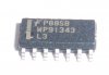
I need a datasheet tho heh.... Thanks ima try to change the numbers a bit and see if i can find a similar IC more public
Closest I got was a WP90224L4, which looks kinda right. 14pin chip and it says it's a logic IC, which would sound like a common cheaper chip that a company might throw away rather than recycle. It's made by AT&T, though.
No they don't but, they tell you what it does and its function.
You didn't have that info did you.
That was all I could find.
At least you know what it is now.
Description
Simultaneous Read/Write operations Data can be continuously read from one bank while executing erase/program functions in another bank Zero latency between read and write operations Flexible BankTM architecture Read may occur in any of the three banks not being written or erased. Four banks may be grouped by customer to achieve desired bank divisions. WP91343 PDF
File Size:213032 KB
Applications
• Thermal overload of Windings • Low Voltage Cutout • Electrically - Isolated Power Supply • Power Off Manual Resaet • Automatic Reset with Minimum Off Delay Timer • UL File Number SA3745 (41AA) • UL/CSA/CE pending on all other ratings
Features
FLock detection The automatic restart circuit detects a motor lock condi- tion and automatically turns off the output current. When the lock condition is cleared, the IC automatically restarts and allow the motor to run. In the WP91343AF, automatic restart is performed as fol- lows. A motor lock condition is detected when the Hall signal stops switching. The output is ON when the LD pin is being charged, and OFF when the pin is being discharged. S The AL pin is ON during normal operation, and OFF when the motor is locked. S The AL pin is an open collector output.
Description
Input voltages exceeding the input overvoltage shutdown specification listed in the Performance/Functional Specifications will cause the device to shut- down. A built-in hysteresis (2V typical for "D24" models, 4V typical for "D48" models) will not allow the converter to restart until the input voltage is sufficiently reduced. WP91343L3 PDF
File Size:213032 KB
Applications
The serial Command mode allows access to the WP91343L3 control and status registers via a serial control port. In this mode the AD0, AD1, and AD2 lines provide register addresses for data passed through the AD7 (DATA) pin under control of the RD and WR lines. A read operation is initiated when the RD line is taken low. The next eight cycles of EXCLK will then transfer out eight bits of the selected address location LSB first. A write takes place by shifting in eight bits of data LSB first for eight consecutive cycles of EXCLK. WR is then pulsed low and data transfer into the selected register occurs on the rising edge of WR.
Features
Please be aware that an important notice concerning availability, standard warranty, and use in critical applications of Texas Instruments semiconductor products and disclaimers thereto appears at the end of this data sheet. ARM7TDMI is a trademark of Advanced RISC Machines (ARM) Limited.
WP91343L3 Features:
Power Dissipation at 25 C Molded DIP Package Board Mount Molded DIP Package Socket Mount Molded DIP Package Board Mount Derate 21 7 mW C Above 25 C Molded DIP Package Socket Mount Derate 19 6 mW C Above 25 C Junction Temperature Lead Temperature (Soldering 10 seconds)
WP91343L3 (Absolute) Maximum Ratings:
DATA Pin The DATA pin is the serial data in (SDI) function for setting the threshold of the voltage comparator. The DATA pin contains an internal Schmitt trigger as part of its input to improve noise immunity. This pin has an inter- nal pullCdown device to provide a low level when the pin is left unconnected. CLK Pin The CLK pin is used to provide a clock used for loading and shifting data into the DATA pin. The data on the DATA pin is clocked into a shift register on the rising edge of the CLK pin signal. The data is transferred to the D/A Register on the eighth falling edge of the CLK pin. This protocol may be han- dled by the SPI or SIOP serial I/O function found on some MCU devices. The CLK pin contains an internal Schmitt trigger as part of its input to improve noise immunity. The CLK pin has an inter- nal pulldown device to provide a low level when the pin is left unconnected.
WP91343L3 Pinout:
Capacitor mounted close to the power module helps ensure stability of the unit, it is recommended to use a good quality low Equivalent Series Resistance (ESR < 1.0[ at 100 KHz) capacitor of a 2.2uF for the 5V input devices, a 1.0uF for the 12V input devices and a 0.47uF for the 24V devices.
TAOperating free-air temperature070_C NOTE 4: The RESET input of the device must be held at valid logic voltage levels (not floating) to ensure proper device operation. The differential inputs must not be floating unless RESET is low. Refer to the TI application report, Implications of Slow or Floating CMOS Inputs, literature number SCBA004.
The control input pin of the regulator. This pin is connected, via a 10V resistor, to the 5V supply to provide the base current for the pass transistor of both regulators. This allows the regulator to have very low dropout voltage which allows one to generate a well regu- lated 2.5V supply from the 3.3V input. A high frequency, 1mF capacitor is connected between this pin and VIN pin to insure stability.
I saw that on my own search, but it looks like just random sentences in order to troll search providers. There's talk of address and data lines, motor control, Texas Instruments and TI app notes, ARM7TDMI,... it's all just random cut and pasted sentences.
I saw that on my own search, but it looks like just random sentences in order to troll search providers. There's talk of address and data lines, motor control, Texas Instruments and TI app notes, ARM7TDMI,... it's all just random cut and pasted sentences.
It doesn't make any sense, one datasheet for a supposedly similar IC coughed up by one of those search engines said it's a DC-DC converter but the manufacturer wasn't Fairchild.
This site uses cookies to help personalise content, tailor your experience and to keep you logged in if you register.
By continuing to use this site, you are consenting to our use of cookies.