Continue to Site

Welcome to our site!

Electro Tech is an online community (with over 170,000 members) who enjoy talking about and building electronic circuits, projects and gadgets. To participate you need to register. Registration is free. Click here to register now.

  • Welcome to our site! Electro Tech is an online community (with over 170,000 members) who enjoy talking about and building electronic circuits, projects and gadgets. To participate you need to register. Registration is free. Click here to register now.

Fading LED

Status
Not open for further replies.

toyds

New Member
Hello All,

I'm new here and want to design a circuit that will FADE the LED to ON/OFF

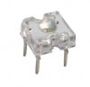
I will be using this LED module

**broken link removed**

it already has a resistor but i don't know the exact value

I will be using a 12V input supply from my motorcycle

12V ---------(switch)--- (+ LED module)
|
|
0V ---------------------(- LED module)

This is the flow
1. When i switch ON the switch the LED Light to its maximum mA and it will automatically fade OFF and vice versa.

i search the internet and found this circuit

https://www.555-timer-circuits.com/up-down-fading-led.html
is this applicable to 12V supply?


please help me design a circuit

thank you very much
 
The circuit contains a single LED. You can use it for a supply voltage of +12V when increasing the value of R3 (now 470Ω) to 560 or 680Ω.

The internal circuit of your module is unknown. So you should connect a single module to 12V and measure the current flow. It should not be higher than the module is rated for.

When the circuit is known you might parallel several modules using a transistor with higher current capabilities such as a BD139.

Boncuk
 
Hello Boncuk,

thank you very much for the reply.i will try to make the circuit and try to connect it in 12V supply.
 
So you should connect a single module to 12V and measure the current flow. It should not be higher than the module is rated for.
I think Boncuk regards one of the five strips shown as 'a single module', whereas you refer to what is shown in the picture as 'a module'. Can you clarify whether there is 1 or 5 'modules' shown ??
WARNING: You must use a current-limiting resistor in series with the module(s), otherwise you risk destroying the LEDs.

It looks as though each strip has 3 white LEDs. Can you confirm?
If your supply is 12V then the maximum number of LEDs in series that you can power directly (i.e. without using a DC-to-DC converter) is 3.

Yes, you're right. Connecting four or five of those (3 LED modules) in parallel makes no sense to me. Each module would have to have its own current limiting resistor in that case. May be it's built in already and the wires just connect before each part of the module?

About like this?

Boncuk
 

Attachments

  • LED-MODULES.gif
    LED-MODULES.gif
    17.6 KB · Views: 317
Last edited:
I guess that each module has three 3.5V SuperFlux white or blue LEDs in series and a 68 ohm series resistor. Each module has a current of 44mA when the supply is 13.8V. Then the total max current for 5 modules in parallel is 220mA which is way too much for a little BC547 transistor.

The fading circuit is designed for a 9V supply and a single LED. It is an oscillator that continuously brightens and fades the LED over and over.
With a 13.8V supply, the output of the fading circuit swings from 3.9V to 8.5V so the modules will never light.
 

Attachments

  • Luxeon SuperFlux LED.jpg
    Luxeon SuperFlux LED.jpg
    4.8 KB · Views: 275
Boncuk design in parallel is what i want.but i need to make the LED fade on/off.

can you please give me a circuit that will work for 12V supply(from motorcycle battery)?i want to make it like an heartbeat effect for a motorshow here in my country(philippines)

please
thank you very much
 
Last edited:

Attachments

  • temp4.GIF
    temp4.GIF
    17.7 KB · Views: 2,595
Last edited:
The circuit you found does not fade the LEDs. Instead it abruptly turns them on and off.
 
Hi toyds,

you might try to use a logic level N-channel MosFet transistor instead of an NPN bipolar transistor as of the original schematic, or use a darlington (bipolar) transistor for low base current and capable to drive 5 chains of LEDs.

I will order a sample of the NXP BUK962R8-30B logic level and experiment with that one.

Boncuk
 
@audioguru : is adding a capacitor can do the job?
The 555 already has a capacitor. With a 13.8V supply, its voltage ramps up to 9.3V and ramps down to 4.6V at a low current over and over. It is useless to drive your LED modules.
 
Status
Not open for further replies.

New Articles From Microcontroller Tips

Back
Top