Continue to Site

Welcome to our site!

Electro Tech is an online community (with over 170,000 members) who enjoy talking about and building electronic circuits, projects and gadgets. To participate you need to register. Registration is free. Click here to register now.

  • Welcome to our site! Electro Tech is an online community (with over 170,000 members) who enjoy talking about and building electronic circuits, projects and gadgets. To participate you need to register. Registration is free. Click here to register now.

exploding traces.

Status
Not open for further replies.

HerbertMunch

New Member
hi,

i was working on a transformer board, stepping down 230v to 12v (9v on diagram) and was checking the 12v and gnd with my scope, but when i connected the ground of the ptobe, a massive arc occured between the gnd lead of the scope and also blew up some of my gnd traces!

I dont understand because i had just checked the same thing with my multimeter and it registered 12v, no problem.

Why would connecting up my scope have caused this?

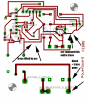
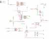
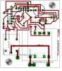
I have included the schematic and the board, showing where the traces exploded.
only the xformer, the relay and the bridge rectifier were connected at the time.

I think that my board took the brunt of the arcing, but could the transformer or the scope be damaged?

I would appreciate your input on this matter.
Many thanks,
chris
 

Attachments

  • board.png
    board.png
    41.7 KB · Views: 187
  • schem.png
    schem.png
    77.8 KB · Views: 182
I think the circuit did not have an earth ground and its transformer was shorted from the live AC power to the secondary or to the circuit's ground (the core of the transformer).
Then your scope had an earth ground which completed a path from the power line's live to ground.
You are lucky you did not get electrocuted.
 
audioguru said:
I think the circuit did not have an earth ground and its transformer was shorted from the live AC power to the secondary or to the circuit's ground (the core of the transformer).
Then your scope had an earth ground which completed a path from the power line's live to ground.
You are lucky you did not get electrocuted.

YOu are saying that his transformer secondary was floating and so when he connected a scope probe which has a connection to ground inside the scope, it made a short?

This is the same thing someone (maybe NIgel?) mentioned in another post about how an isolation transformer can be defeated by using a scope that has a internal ground connection to it's ground probe?
 
Are you sure that the relay connections either side of the one marked common are not the coil connections? Like this,
**broken link removed**
That or a shorted transformer are the only way it could short out.

Mike.
 
I think that your relay is wired wrong. It looks Ok in the schematic, but on the PCB layout it appears that you've mixed up the coil connections with the NO and NC contacts!
 
Exploded traces

No mystery for me! You used a GND from the bridge rectifier and a GND from the center tap of the primary windings of the transformer.
 
Boncuk said:
No mystery for me! You used a GND from the bridge rectifier and a GND from the center tap of the primary windings of the transformer.
There isn't a center tap on the primary.:confused:

Mike.
 
Your meter didn't have a problem because it is battry operated and so is isolated from the AC. But, your o-scope's supply is probably an AC/DC unit, so has a connection back to the NEUTRAL/GROUND common connection at the main box. The ground clip on your probe is hooked into this system. I've "fused" a few traces myself this way. This is why I always keep a two-pronged cheater on my o-scope's power plug. This means there is no protection by way of the grounded chassis, so can be a dangerous thing. 'Wish I'd had the extra money for the battery option. Then I'd have had isolation by default.

Late(zz-r-appp!)
kenjj
 
Always check the connection of the relay pins using a meter before use. There is no universal configuration of pin location. Your assumption of the three switch contacts all on the same end has costed you only the board this time. The oscilloscope is probably still good and you are not hurt.

Should you have following someone's ill advice and have disconnected the earth of the oscilloscope, you might not notice anything until you try to operate the control of the oscilloscope and then get electrocuted.
 
Thanks all for your replies.

Luckily, this being my first time dabbling with the dangers of mains electricity, I was keeping my distance from the entire board, and had glued it down to a test surface along with a terminal strip, and all the wiring.
I only had two leads coming from the board which were hooked up to insulated croc clips. At no point did i come into contact with any bare metal.

I was quite shocked (not electrically) by the massive arc that occured, but was not injured.

The transformers primary winding is fried (infinate resistance) but the scope seems to be ok.

i just assumed that the three pins were the switch parts and the two on their own were the coil. Stupid me.

Ive got the datasheet for the relay: https://www.electro-tech-online.com/custompdfs/2008/02/f36xx.pdf
I glanced at it and obviously got the wrong end of the stick about the diagram.

Why would having the relay wrong cause this though?

thanks all.
 
Last edited:
I just looked at the underside of the relay! it says the connections on there. it never occured to me that the pins might not be logically placed.
 
Pommie said:
There isn't a center tap on the primary.:confused:

Mike.

Of course I meant secondary. (Language barrier sometimes) :)
 
Herbert, your PCB should have a location for an on board fuse. Always fuse circuits that connect to power, especially AC wall socket power.

I'll bet that if you disassemble the bad transformer, that you will find a blown internal current-and-heat sensitive fuse where the primary wires connect to the primary windings.

Bob
 
Bob Scott said:
Herbert, your PCB should have a location for an on board fuse. Always fuse circuits that connect to power, especially AC wall socket power.

I'll bet that if you disassemble the bad transformer, that you will find a blown internal current-and-heat sensitive fuse where the primary wires connect to the primary windings.

Bob

Do i need to fuse the board if the plug has a fuse in it?

I opened the casing of the transformer, but cant open it further:mad: I cant seem to seperate the pieces.

thanks
 
HerbertMunch said:
also, how come my house circuit breaker didn't trip?

Modern UK consumer units are fitted with a 30mA RCD supplying the ring sockets circuits.

Older types may not have it or may have a less sensitive RCD fitted.

You may need to just check your consumer unit has a working RCD (there is a test button on it) and if necessary, use a separate plug-in type rcd for your electronics workbench for now if you don't have adequate rcd protection.
 
@HerbertMunch,

It sounds to us you are still unsure why your traces blew up. We have given you the correct cause and you need to make sure you understand why this connection error had resulted in the blown traces.

Hint: Think of relay contact as closed between (Common and N.C.) and will conduct current from the common center pin to any circuit having a connection to the N.C. contact pin. If you put LIVE on the center pin, then the N.C. pin will be at live potential too. Did you connect anything to the N.C. pin?

The scope lead clip is earthed, did you touch this earthed clip to any point on circuit which has LIVE potential?
 
Chris,
Just rebuild the circuit, there is a good chance the transformer is not damaged as the PCB tracks acted as your fuse. However, you were lucky this time, had you handled the low voltage side of the board you could have been electrocuted. Hopefully, your first big bang scared the xxxx out of you as it did me and you will double check everything involving mains in the future. I had a very good friend who lost his life through a silly mistake like this.

Mike.
 
Status
Not open for further replies.

Latest threads

New Articles From Microcontroller Tips

Back
Top