Continue to Site

Welcome to our site!

Electro Tech is an online community (with over 170,000 members) who enjoy talking about and building electronic circuits, projects and gadgets. To participate you need to register. Registration is free. Click here to register now.

  • Welcome to our site! Electro Tech is an online community (with over 170,000 members) who enjoy talking about and building electronic circuits, projects and gadgets. To participate you need to register. Registration is free. Click here to register now.

experienced members please help with this diagram

Status
Not open for further replies.

heyhi

New Member
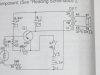
this is a light controlled chirping bird can some 1 explain how the components are working together to make this work. i got it on a lab kit bread board. I'm trying to test each component to see how they work i get 4.7 volts to the emitor and cap the neg side of the cap gets 4.3 to the cds.. i tryed testing the current i Have a fluke ... used Milli A 1 lead on 1 side of component and the other lead on the other side I'm not getting any reading but its working ,,,some 1 please help explain what to do to test current and how this circuit and each component is doing its job. please explain how and why the ceramic cap stops voltage to the transformer and why ect... how each component works...
 

Attachments

  • light controled bird.zip
    1.6 MB · Views: 155
Last edited:
Reattach your image as a jpega rather than a zipped jpeg and maybe more people will bother to look.

To me it looks like an amplifier driving a speaker where the amplifier's input signal is the signal from a photodetector.
 
heyhi said:
...used Milli A 1 lead on 1 side of component and the other lead on the other side...
You can't measure current through a component like that. You have to lift one leg of the component and connect the meter between the lifted leg and the circuit point it was attached to; the internal resistance of the meter will complete the circuit. If the component you want to measure current through happens to be a resistor of known (measured, not nominal) value, you can take a shortcut and leave it in place while measuring the voltage drop across it and applying Ohm's Law.
 
its the only way i can fit the pic to the atachment
 
It is called a blocking oscillator. When power is applied, Q1 turns on slightly because it is biased via the LDR and the 50K pot. When Q1 turns on it causes a current to flow in the transformer. This causes the voltage on terminal 39 of the transformer to go more negative turning the transistor on more via C1. This continues until the transformer core saturates. Once it saturates, the magnetic field collapses, driving terminal 39 of the transformer positive and thus turning off Q1. Once the field fully collapses, Q1 will be turned on again and the cycle repeats.
Your diagram didn't need to be that big. Here is a scaled down version (36K vs 1590K) :
 

Attachments

  • light controled bird.JPG
    light controled bird.JPG
    36.5 KB · Views: 267
Last edited:
heyhi said:
its the only way i can fit the pic to the atachment

Instead of jpeg or zipped jpeg, save your schem in png format
it will half the size and ensure many more people will look.:)
 
Status
Not open for further replies.

New Articles From Microcontroller Tips

Back
Top