Continue to Site

Welcome to our site!

Electro Tech is an online community (with over 170,000 members) who enjoy talking about and building electronic circuits, projects and gadgets. To participate you need to register. Registration is free. Click here to register now.

  • Welcome to our site! Electro Tech is an online community (with over 170,000 members) who enjoy talking about and building electronic circuits, projects and gadgets. To participate you need to register. Registration is free. Click here to register now.

Eqlizer circuit for review and suggestions

Status
Not open for further replies.

MrDEB

Well-Known Member
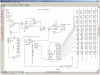
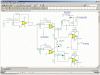
this is ONLY one channel, ONE of ten filters and ONE of 10
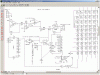
bi-lateral switches.
A version of the Vellman equalizer circuit.
the diode/capacitor feeding the lm3916 acts as a peak detector for the display
the 4017 cycles the bi lateral switches acting as a multiplexer.
Any comments welcome
NOTE this is an abreviated version of entire circuit
 

Attachments

  • brief eq circuit.GIF
    brief eq circuit.GIF
    88.6 KB · Views: 268
Don't know why but click on the pic then left click the magnifyer to define the gif pic.
?????????
 
MrDEB said:
Don't know why but click on the pic then left click the magnifyer to define the gif pic.
?????????

It's because the image is too big to show in the current window, so the browser is automatically scaling it down to fit. When this happens, the magnifier cursor is offered to allow you the option of viewing the image at its original size.

Are you using FireFox?


Torben
 
This equalizer adjusts of the level of a band of frequencies down to zero. Equalizers usually adjust the amount of boost and cut equally because their adjustment pot is in the feedback loop of an opamp.

The signal feeding the bi-lateral switch is zero volts because it is the virtual ground input of the following opamp.

The filter should feed an RC peak detector that should feed the bi-lateral switch.

The input of the LM3916 needs a resistor (1M) to ground.

The LEDs will be extremely dim because the average current in each will be divided by 10 due to the multiplexing.

If your project was in a single topic then things will be easier to find such as the original Velleman circuit and the Oriental display project.
 
The signal feeding the bi-lateral switch is zero volts because it is the virtual ground input of the following opamp.
Maybe connect BEFORE the pot?

The filter should feed an RC peak detector that should feed the bi-lateral switch.
I take it the diode/capacitor won't do the deed? Maybe insert the diode/capacitor before the bi-latteral switch? I contemplated this approach.

The input of the LM3916 needs a resistor (1M) to ground.
Reason??

The LEDs will be extremely dim because the average current in each will be divided by 10 due to the multiplexing.

I kinda copied the oriental circuit in combination with the Vellman circuit (the 2067 no longer available) so I am using a lm3916. not real sure it will work but you may be right on tooo dim.
any suggestions?
 
MrDEB said:
The signal feeding the bi-lateral switch is zero volts because it is the virtual ground input of the following opamp.
Maybe connect BEFORE the pot?
The filter's level control should feed the audio output opamp plus feed a buffer opamp that feeds the peak detector diode. Before the pot won't show changes to the response made by the equalizer.

The filter should feed an RC peak detector that should feed the bi-lateral switch.
I take it the diode/capacitor won't do the deed? Maybe insert the diode/capacitor before the bi-latteral switch? I contemplated this approach.
Yes, the diode-capacitor peak detector should be fed from a buffer opamp so that the peak detector doesn't cause distortion. The bi-lateral switch needs to route the level from each peak detector to the LM3916 one-at-a-time, not having then all paralelled together.

The input of the LM3916 needs a resistor (1M) to ground.
Reason??
The input of an LM391x is a PNP transistor that floats high if the input doesn't have a 1M resistor as a pull-down.

The LEDs will be extremely dim because the average current in each will be divided by 10 due to the multiplexing.
I kinda copied the oriental circuit in combination with the Vellman circuit (the 2067 no longer available) so I am using a lm3916. not real sure it will work but you may be right on tooo dim.
any suggestions?
The Velleman circuit has a powerful transistor driving both ends of the LEDs.
Add a transistor to each output of the LM3916.
 
Last edited:
circuit revisions

here are the revisions suggested.
The peak detector circuit is basically cycled via the 4017?
hope this is what you are refering to in last post?
as to revising the possible grounding of the op amps input--would adding a 1K resistor to ground do the deed in series with the pot?
 

Attachments

  • revised circuit.GIF
    revised circuit.GIF
    87.9 KB · Views: 163
The new U3 opamp in the center of the schematic (please number parts separately) is an inverter with an extremely low input impedance and it is connected where there is no signal voltage. It needs to be a high input impedance buffer and its input can be the slider of the pot or the output of the filter.

The peak detector must be driven from the output of U3. The output of the bi-lateral switch feeds the input of the LM3916.

The new transistor is turned off by the LM3916 when the LEDs must light so it won't work. I think you have plenty of supply voltage so the new transistor can be a PNP emitter-follower. It will need a pullup resistor from base to emitter to turn it off.

Add on the schematic a note where all the filters' 100k resistors from their volume controls connect to the input of the output opamp, and where the outputs of all the bi-lateral switches feed the input of the LM3916.
 
will make revisions

looked over the Vellman circuit again, this time the filters which have an additional op amp per filter.
need to address this better.
Also the oriental circuit has an additional transistor in its display.
will revise and renumber when doing COPY
 
peak detector revisions

I think I solved the filter output problem of zero voltage.
I added a resistor in series w/ pot(R4) and added transistor circuit to filter output.
added C4 as the circuit wouldn't work otherwise??
The T1/D3 output connected to bi-lateral circuit.
 

Attachments

  • peak detector revision.GIF
    peak detector revision.GIF
    64.2 KB · Views: 510
The peak detector will take all day to charge. It is supposed to be fed from the low impedance output of an opamp so it can charge the capacitor very quickly, not fed from a 100k resistor.

The output opamp does not receive audio anymore. It receives DC instead.

D1 and R6 are not needed.
 
changed input to op amp etc

took care of the dc issue and moved the input of output stage so 100k resistor no longer feeding.
I really appreciate all your input
I think the glitch is showing that the peak detector is working?
 

Attachments

  • wave pic.GIF
    wave pic.GIF
    111.3 KB · Views: 156
No.
the peak detector diode needs to be fed from the low output resistance of a new buffer opamp so the capacitor charges very quickly, not from the 100k resistor and pot that take a long time to charge it.

I don't remember what the transistors are for and I don't want to search through all your threads to find which original circuit has them.
 
transistor for display

the transistor is driving the 10x10 led display. The base is controlled by a 4017 counter
The added resistor between the pot and ground works as you predicted.
Will revise the peak detector section.
Will probaly end up with additional TL074's
The op amps that are used for the filters may become TLC074's (TI updated op amp. available from mouser in a quad PDIP package (PDIP ??)
was planning on LM837 but mouser dosn't carry them (want to order from one place to save shipping)
 

Attachments

  • peak detector revision.GIF
    peak detector revision.GIF
    64.2 KB · Views: 146
I compared the TL074 and the LM387 and didn't hear any difference.
They are both low noise, have very low distortion and have a bandwidth to 100kHz.

Please get rid of D1 and R6. They are absolutely useless and hurt my eyes.
 
lets try again

attached pic
do you have TINA? I can send you the compressed file as well?
 

Attachments

  • peak detector revisions.GIF
    peak detector revisions.GIF
    94.4 KB · Views: 159
  • bandpass filter11.zip
    400 bytes · Views: 109
I don't use Tina.

I saw the peak detector in the LM3915 datasheet.
I think it should be fed from the very low output resistance of an opamp, not from the high resistance of the level control plus 100k. The transistor will cause distortion in the audio when its base voltage is driven below -0.7V.

I sketched a peak detector that is similar and uses an opamp as a high input resistance buffer.
 

Attachments

  • peak detector2.PNG
    peak detector2.PNG
    6.3 KB · Views: 151
Status
Not open for further replies.

Latest threads

New Articles From Microcontroller Tips

Back
Top