Hi,
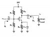
Q(1)Given a amplifier circuit of a mosfet trasistor, how do we employ to determine values of c1, c2 and Cs?
Q(2) For an op-amo, what's the usage or function of resistor at + of the op-amp? Does they affect the performace of the amplifier circuit?
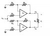
Q(3) what's the usage of having differential amplifier and current mirror amplifier?
Q(1)Given a amplifier circuit of a mosfet trasistor, how do we employ to determine values of c1, c2 and Cs?
Q(2) For an op-amo, what's the usage or function of resistor at + of the op-amp? Does they affect the performace of the amplifier circuit?
Q(3) what's the usage of having differential amplifier and current mirror amplifier?