Continue to Site

Welcome to our site!

Electro Tech is an online community (with over 170,000 members) who enjoy talking about and building electronic circuits, projects and gadgets. To participate you need to register. Registration is free. Click here to register now.

  • Welcome to our site! Electro Tech is an online community (with over 170,000 members) who enjoy talking about and building electronic circuits, projects and gadgets. To participate you need to register. Registration is free. Click here to register now.

Enquiry

Status
Not open for further replies.

shermaine

New Member
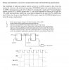
I have got a project, it has a dip switch which control the scale of 0 - 5.
After pressing the pushbutton switch, the timing of the led will light up depending
on the scale.If the scaled is 0 to 3, the green led flashes for 16 times.
If the scale is 3 to 5, the red led flahes for 3 x scale times and after which green
led is flashed for the next (16-(3xscale)) seconds.
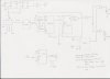
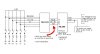
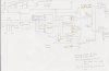
For the led timing, i can use binary adder(74283) and the synchronous 4 bit up/down
counter with mode control(74191) I also need a J/K ff with reset & clear function right,
to check & reset the led.
Do i need a 4 bit comparartor (7485) to know whether the scale it is in is 0 to 3 or 3 to 5?
What chip shouild i use to connect at the dip switch or puish button switch?
 
hi shermaine,

First reaction is that this project is ideally suited for a PIC.

If you have the facilities for PIC usage, I would suggest that you consider using a PIC.

I'll have another look thru your text to see if I can help using the chip logic you have described.

Eric
 
hi shermaine,

Studied your text, I'm having a little difficulty is visualising how your logic ic's are interconnected.

Do you have a rough/working sketch you could post?

Eric.
 
here's the layout of the ic and anything i can amend from there?
 

Attachments

  • ee.JPG
    ee.JPG
    125.8 KB · Views: 232
Last edited:
Hi,
Looking over your circuit I have the following observations.
Assuming the drawing is correct, its a very complex way of trying to flash the LED's in the way you describe.

What purpose is the 74175, connected to the bit switch, serving?

The Ax/Bx inputs of the 74283 adder are linked together, so its always adding the same pair of numbers.
Its just left shifting the bit switch value, by one.?

Where is the'clk' signal coming from?

You are clocking the 74191 [bottom one] with 'A' to give a 15 divide by signal 'B' [you say, ripple clk???], which are used as 'J' and 'K' inputs to the 74109.

Can you let us know what the projects for and whats it purpose.?

Eric
 
ericgibbs said:
Hi,
Can you let us know what the projects for and whats it purpose.?

Eric

Yes, please. Digital circuits are based upon logic, not magic.
 
The 74175 was given in the project as starting point.

Yes, so that the led will keep counting on.

I'm confused with the clk signal.Where should i clk it?Can advise me?


It act as a alarm alert system.
 
Hi Shermaine

Attached is a little something that might get your thinking started. It is not meant to be exact or complete, and leaves you with plenty to learn and do.
 

Attachments

  • Dec2BCD.JPG
    Dec2BCD.JPG
    28.5 KB · Views: 142
Thanks for the info.
But based on my layout, can u guys advise me if there is any thing that i need to amend? Please advise. Thanks.
 
here's the q. can anyone advise me what i should amend the lauyout so that i can start wiring the breadboard componnets. thanks.
 

Attachments

  • q.JPG
    q.JPG
    57.8 KB · Views: 156
hi shermaine,

I keep looking at your circuits and the project description and I cannot see how your original circuit will do what you want.

It would be easier and simpler to start with a fresh look at at totally different circuit design.

I know this is not a positive response, but for me to do so, would require me to do a complete redesign.
If this is a school/study project, this would not help you, if I did it for you.

I'm puzzled why your tutor gave you the 74175 as a starting point.

Please respond.

Regards
Eric
 
Hi Eric,

I have redone again. Can you advise me if i need to amend any part immediately? Thanks.
 

Attachments

  • lay-out.JPG
    lay-out.JPG
    150.5 KB · Views: 132
For IC 74175 and 74109, there have got CLR function pin.
I do not want to clear. How should i connect in such a way to disable clear?
 
hi shermaine,

On the 74175, pin 1 CLR, connect it to +5V thru a 2K2 resistor.

74109, do you mean 74191?

If Yes, which pin number do you mean, cannot see a CLR on the ic diagram?

If you mean pin 4, 'Enable' connect it to 0V, to enable the counter.

Eric
 
Last edited:
Status
Not open for further replies.

Latest threads

Back
Top