Continue to Site

Welcome to our site!

Electro Tech is an online community (with over 170,000 members) who enjoy talking about and building electronic circuits, projects and gadgets. To participate you need to register. Registration is free. Click here to register now.

  • Welcome to our site! Electro Tech is an online community (with over 170,000 members) who enjoy talking about and building electronic circuits, projects and gadgets. To participate you need to register. Registration is free. Click here to register now.

energy harvesting low voltage sources - MFC

Status
Not open for further replies.

twilk

New Member
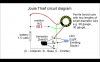
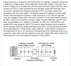
I'm wondering if transistors can be used to automatically switch back and forth between 2 banks of capacitors? The low voltage power source (microbial fuel cell) needs to charge one bank while the other is discharging, without risk of polarity reversal (which the capacitors may protect against?). Does anyone here know where I can find this info? I'll be using a breadboard and some basic components to experiment with this idea but I'm not sure where to start. I have a bank of MFCs producing between 1.8 and 2.2 volts.
 
Welcome to ETO, twilk!

Yes, but...

Can you give us a schematic of what you have designed and/or bread-boarded thus far?

Have you considered SMPS "boost" circuits? Might make the process a little more controllable.
 
DSCF3590.JPG
 
Two 2N 4401 transistors, 1.8v LED, 25v 2.2 capacitor on the right, 3 capacitors in parallel on the left (50v 3.3). I don't know what the toroids are rated at. This drove five 2.2v LEDs (white/yellow, green and two reds) on a rechargeable AA battery at 1.1v. Powered by the 2v MFC it drove two 2.2v LEDs but the voltage dropped from the source and the AA battery recharged by .2v - then the lights dimmed and the system lost it's advantage.
 
Last edited:
Here's the plan I used for the two joule thieves that I connected in series.
 

Attachments

  • Screen Shot 2014-08-05 at 6.07.20 PM.png
    Screen Shot 2014-08-05 at 6.07.20 PM.png
    268.8 KB · Views: 1,131
Here's what I want to add but I haven't figured out how to do it yet.
 

Attachments

  • Screen Shot 2014-08-12 at 1.58.38 PM.png
    Screen Shot 2014-08-12 at 1.58.38 PM.png
    143.2 KB · Views: 557
A "charge pump" is very close to what you are trying to do.

It appears you want to have two banks, one charging and one discharging.
I think CowBoyBob is right. Use a PWM boost circuit (low voltage to high voltage) and only have one bank.

See attached data sheet. 0.9 to 1.8V to 3.3V charge pump If this is close then there are many different kinds of these. This type of charge pump would work with only one set of capacitors.
 

Attachments

  • tps60300.pdf
    538.7 KB · Views: 510
One LED is fairly bright at 10mA to 20mA. If your fuel cell develops a current of 1mA at 1.5V then when the 1.5V is stepped up (with a Joule Thief) to 4.5V to light the LED the current to the LED is reduced to only 1.5/4.5 x 1mA= 0.33mA (if the stepup circuit has no loss) and the LED will be very dim. Maybe the circuit can charge a capacitor for 1 hour then light the LED brightly for 1 minute? No, the LED will start the minute brightly, slowly dim for 30 seconds then not light anymore for the other half minute.
 
Status
Not open for further replies.

New Articles From Microcontroller Tips

Back
Top